Infiniti EX35. Manual — part 1149
PCS
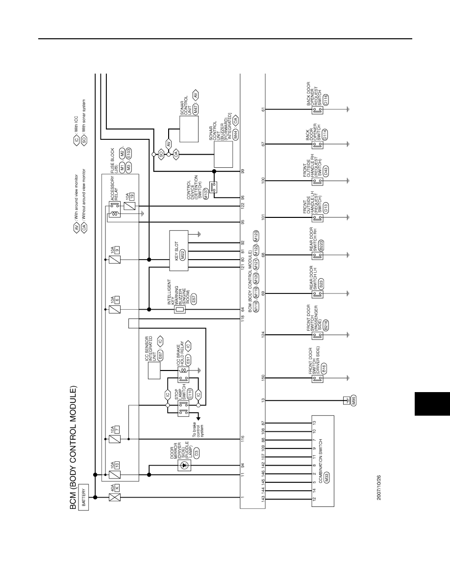
BCM (BODY CONTROL MODULE)
PCS-97
< ECU DIAGNOSIS >
[POWER DISTRIBUTION SYSTEM]
C
D
E
F
G
H
I
J
K
L
B
A
O
P
N
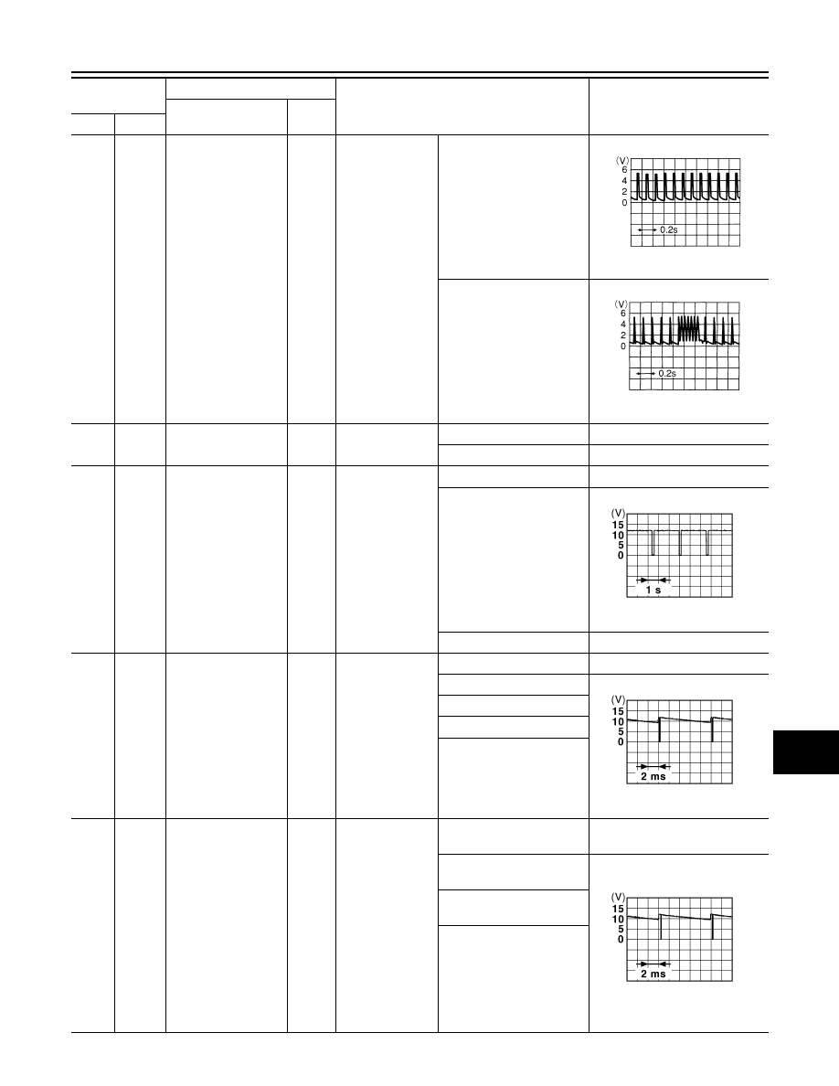
139
(L)
Ground
Tire pressure receiv-
er signal
Input/
Output
Ignition switch
ON
Standby state
When receiving the signal
from the transmitter
140
(GR)
Ground
Selector lever P/N
position signal
Input
Selector lever
P or N position
Battery voltage
Except P and N positions
0 V
141
(G)
Ground
Security indicator sig-
nal
Output
Security indicator
ON
0 V
Blinking
11.3 V
OFF
Battery voltage
142
(O)
Ground
Combination switch
OUTPUT 5
Output
Combination
switch
(Wiper intermit-
tent dial 4)
All switch OFF
0 V
Lighting switch 1ST
10.7 V
Lighting switch HI
Lighting switch 2ND
Turn signal switch RH
143
(P)
Ground
Combination switch
OUTPUT 1
Output
Combination
switch
All switch OFF
(Wiper intermittent dial 4)
0 V
Front wiper switch HI
(Wiper intermittent dial 4)
10.7 V
Rear wiper switch INT
(Wiper intermittent dial 4)
Any of the conditions below
with all switch OFF
• Wiper intermittent dial 1
• Wiper intermittent dial 2
• Wiper intermittent dial 3
• Wiper intermittent dial 6
• Wiper intermittent dial 7
Terminal No.
(Wire color)
Description
Condition
Value
(Approx.)
Signal name
Input/
Output
+
–
OCC3881D
OCC3880D
JPMIA0014GB
JPMIA0031GB
JPMIA0032GB
PCS-98
< ECU DIAGNOSIS >
[POWER DISTRIBUTION SYSTEM]
BCM (BODY CONTROL MODULE)
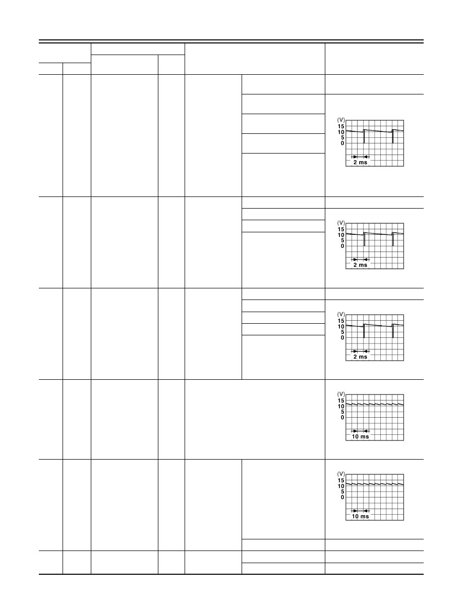
144
(G)
Ground
Combination switch
OUTPUT 2
Output
Combination
switch
All switch OFF
(Wiper intermittent dial 4)
0 V
Front washer switch ON
(Wiper intermittent dial 4)
10.7 V
Rear wiper switch ON
(Wiper intermittent dial 4)
Rear washer switch ON
(Wiper intermittent dial 4)
Any of the conditions below
with all switch OFF
• Wiper intermittent dial 1
• Wiper intermittent dial 5
• Wiper intermittent dial 6
145
(L)
Ground
Combination switch
OUTPUT 3
Output
Combination
switch
(Wiper intermit-
tent dial 4)
All switch OFF
0 V
Front wiper switch INT
10.7 V
Front wiper switch LO
Lighting switch AUTO
146
(SB)
Ground
Combination switch
OUTPUT 4
Output
Combination
switch
(Wiper intermit-
tent dial 4)
All switch OFF
0 V
Front fog lamp switch ON
10.7 V
Lighting switch 2ND
Lighting switch PASS
Turn signal switch LH
149
(W)
Ground
Tire pressure warn-
ing check switch
Input
Ignition switch ON
11.8 V
150
(LG)
Ground
Driver door switch
Input
Driver door
switch
OFF (Door close)
11.8 V
ON (Door open)
0 V
151
(G)
Ground
Rear window defog-
ger relay
Output
Rear window de-
fogger
Active
0 V
Not activated
Battery voltage
Terminal No.
(Wire color)
Description
Condition
Value
(Approx.)
Signal name
Input/
Output
+
–
JPMIA0033GB
JPMIA0034GB
JPMIA0035GB
JPMIA0011GB
JPMIA0011GB
PCS
BCM (BODY CONTROL MODULE)
PCS-99
< ECU DIAGNOSIS >
[POWER DISTRIBUTION SYSTEM]
C
D
E
F
G
H
I
J
K
L
B
A
O
P
N
NOTE:
*: With auto light system
Wiring Diagram - BCM -
INFOID:0000000003786302
JCMWM1398GB
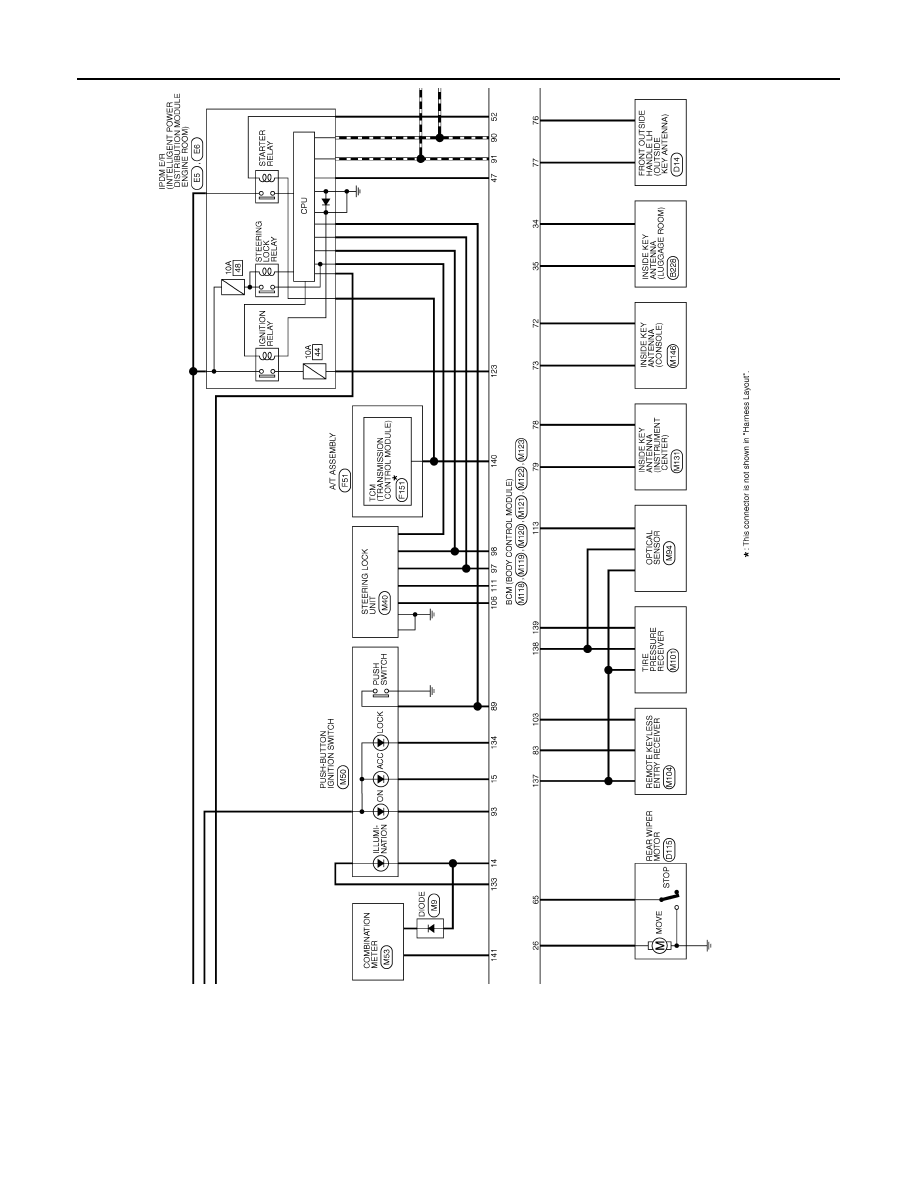
PCS-100
< ECU DIAGNOSIS >
[POWER DISTRIBUTION SYSTEM]
BCM (BODY CONTROL MODULE)
JCMWM1399GB
Нет комментариевНе стесняйтесь поделиться с нами вашим ценным мнением.
Текст