Infiniti EX35. Manual — part 644

EC-318
< COMPONENT DIAGNOSIS >
[VQ35HR]
P0456 EVAP CONTROL SYSTEM
• EVAP canister for damage
• EVAP hose between EVAP canister and vehicle frame for clogging or poor connection
>> Repair hose or replace EVAP canister.
10.
CHECK EVAP CANISTER PURGE VOLUME CONTROL SOLENOID VALVE OPERATION
With CONSULT-III
1.
Disconnect vacuum hose connected to EVAP canister purge volume control solenoid valve at EVAP ser-
vice port.
2.
Start engine and let it idle.
3.
Select “PURG VOL CONT/V” in “ACTIVE TEST” mode.
4.
Touch “Qu” on CONSULT-III screen to increase “PURG VOL CONT/V” opening to 100%.
5.
Check vacuum hose for vacuum.
Is the inspection result normal?
YES
>> GO TO 13.
NO
>> GO TO 12.
11.
CHECK EVAP CANISTER PURGE VOLUME CONTROL SOLENOID VALVE OPERATION
Without CONSULT-III
1.
Start engine and warm it up to normal operating temperature.
2.
Stop engine.
3.
Disconnect vacuum hose connected to EVAP canister purge volume control solenoid valve at EVAP ser-
vice port.
4.
Start engine and let it idle for at least 80 seconds.
5.
Check vacuum hose for vacuum when revving engine up to 2,000 rpm.
Is the inspection result normal?
YES
>> GO TO 14.
NO
>> GO TO 12.
12.
CHECK VACUUM HOSE
Check vacuum hoses for clogging or disconnection. Refer to
Is the inspection result normal?
YES
>> GO TO 13.
NO
>> Repair or reconnect the hose.
13.
CHECK EVAP CANISTER PURGE VOLUME CONTROL SOLENOID VALVE
EC-281, "Component Inspection"
Is the inspection result normal?
YES
>> GO TO 14.
NO
>> Replace EVAP canister purge volume control solenoid valve.
14.
CHECK FUEL TANK TEMPERATURE SENSOR
EC-230, "Component Inspection"
Is the inspection result normal?
YES
>> GO TO 15.
NO
>> Replace “fuel level sensor unit and fuel pump”.
15.
CHECK EVAP CONTROL SYSTEM PRESSURE SENSOR
EC-296, "Component Inspection"
Is the inspection result normal?
YES
>> GO TO 16.
NO
>> Replace EVAP control system pressure sensor.
Vacuum should exist.
Vacuum should exist.

P0456 EVAP CONTROL SYSTEM
EC-319
< COMPONENT DIAGNOSIS >
[VQ35HR]
C
D
E
F
G
H
I
J
K
L
M
A
EC
N
P
O
16.
CHECK EVAP PURGE LINE
Check EVAP purge line (pipe, rubber tube, fuel tank and EVAP canister) for cracks or improper connection.
Refer to
Is the inspection result normal?
YES
>> GO TO 17.
NO
>> Repair or reconnect the hose.
17.
CLEAN EVAP PURGE LINE
Clean EVAP purge line (pipe and rubber tube) using air blower.
>> GO TO 18.
18.
CHECK EVAP/ORVR LINE
Check EVAP/ORVR line between EVAP canister and fuel tank for clogging, kink, looseness and improper con-
nection. For location, refer to
Is the inspection result normal?
YES
>> GO TO 19.
NO
>> Repair or replace hoses and tubes.
19.
CHECK RECIRCULATION LINE
Check recirculation line between filler neck tube and fuel tank for clogging, kink, cracks, looseness and
improper connection.
Is the inspection result normal?
YES
>> GO TO 20.
NO
>> Repair or replace hose, tube or filler neck tube.
20.
CHECK REFUELING EVAP VAPOR CUT VALVE
EC-467, "Component Inspection"
Is the inspection result normal?
YES
>> GO TO 21.
NO
>> Replace refueling EVAP vapor cut valve with fuel tank.
21.
CHECK FUEL LEVEL SENSOR
MWI-58, "Component Inspection"
.
Is the inspection result normal?
YES
>> GO TO 22.
NO
>> Replace “fuel level sensor unit and fuel pump”.
22.
CHECK INTERMITTENT INCIDENT
GI-38, "Intermittent Incident"
.
>> INSPECTION END
Component Inspection
INFOID:0000000003133462
1.
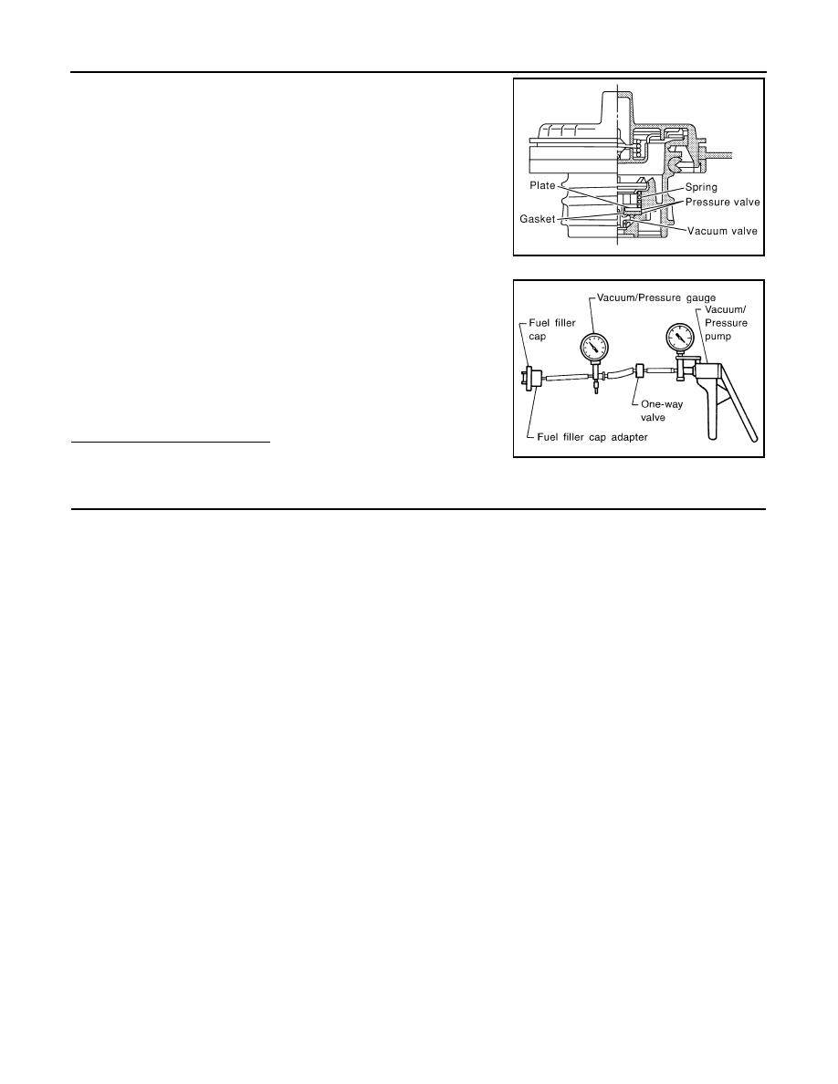
CHECK FUEL FILLER CAP
1.
Turn ignition switch OFF.
2.
Remove fuel filler cap.
EC-320
< COMPONENT DIAGNOSIS >
[VQ35HR]
P0456 EVAP CONTROL SYSTEM
3.
Wipe clean valve housing.
4.
Install fuel filler cap adapter (commercial service tool) to fuel
filler cap.
5.
Check valve opening pressure and vacuum.
Is the inspection result normal?
YES
>> INSPECTION END
NO
>> GO TO 2.
2.
REPLACE FUEL FILLER CAP
Replace fuel filler cap.
CAUTION:
Use only a genuine fuel filler cap as a replacement. If an incorrect fuel filler cap is used, the MIL may
come on.
>> INSPECTION END
SEF445Y
Pressure:
15.3 - 20.0 kPa (0.156 - 0.204 kg/cm
2
, 2.22 -
2.90 psi)
Vacuum:
−
6.0 to
−
3.3 kPa (
−
0.061 to
−
0.034 kg/cm
2
,
−
0.87 to
−
0.48 psi)
SEF943S

P0460 FUEL LEVEL SENSOR
EC-321
< COMPONENT DIAGNOSIS >
[VQ35HR]
C
D
E
F
G
H
I
J
K
L
M
A
EC
N
P
O
P0460 FUEL LEVEL SENSOR
Description
INFOID:0000000003133463
The fuel level sensor is mounted in the fuel level sensor unit.
The sensor detects a fuel level in the fuel tank and transmits a signal to the “unified meter and A/C amp.”. The
“unified meter and A/C amp.” sends the fuel level sensor signal to the ECM through CAN communication line.
It consists of two parts, one is mechanical float and the other is variable resistor. Fuel level sensor output volt-
age changes depending on the movement of the fuel mechanical float.
DTC Logic
INFOID:0000000003133464
DTC DETECTION LOGIC
NOTE:
• If DTC P0460 is displayed with DTC U1000 or U1001, first perform the trouble diagnosis for DTC
• If DTC P0460 is displayed with DTC P0607, first perform the trouble diagnosis for DTC P0607. Refer
.
When the vehicle is parked, naturally the fuel level in the fuel tank is stable. It means that output signal of the
fuel level sensor does not change. If ECM senses sloshing signal from the sensor, fuel level sensor malfunc-
tion is detected.
DTC CONFIRMATION PROCEDURE
1.
PRECONDITIONING
If DTC Confirmation Procedure has been previously conducted, always turn ignition switch OFF and wait at
least 10 seconds before conducting the next test.
>> GO TO 2.
2.
PERFORM DTC CONFIRMATION PROCEDURE
1.
Start engine and wait maximum of 2 consecutive minutes.
2.
Check 1st trip DTC.
Is 1st trip DTC detected?
YES
>> Go to
NO
>> INSPECTION END
Diagnosis Procedure
INFOID:0000000003133465
1.
CHECK DTC WITH “UNIFIED METER AND A/C AMP.”
MWI-40, "CONSULT-III Function (METER/M&A)"
.
Is the inspection result normal?
YES
>> GO TO 2.
NO
>> Go to
.
2.
CHECK INTERMITTENT INCIDENT
GI-38, "Intermittent Incident"
.
>> INSPECTION END
DTC No.
Trouble diagnosis name
DTC detecting condition
Possible cause
P0460
Fuel level sensor circuit
noise
Even though the vehicle is parked, a signal be-
ing varied is sent from the fuel level sensor to
ECM.
• Harness or connectors
(The CAN communication line is open or
shorted)
• Harness or connectors
(The sensor circuit is open or shorted)
• Unified meter and A/C amp.
• Fuel level sensor
Нет комментариевНе стесняйтесь поделиться с нами вашим ценным мнением.
Текст