Infiniti EX35. Manual — part 576
EC-46
< FUNCTION DIAGNOSIS >
[VQ35HR]
ELECTRIC IGNITION SYSTEM
4.
EVAP canister vent control valve
5.
EVAP control system pressure sen-
sor
: Vehicle front
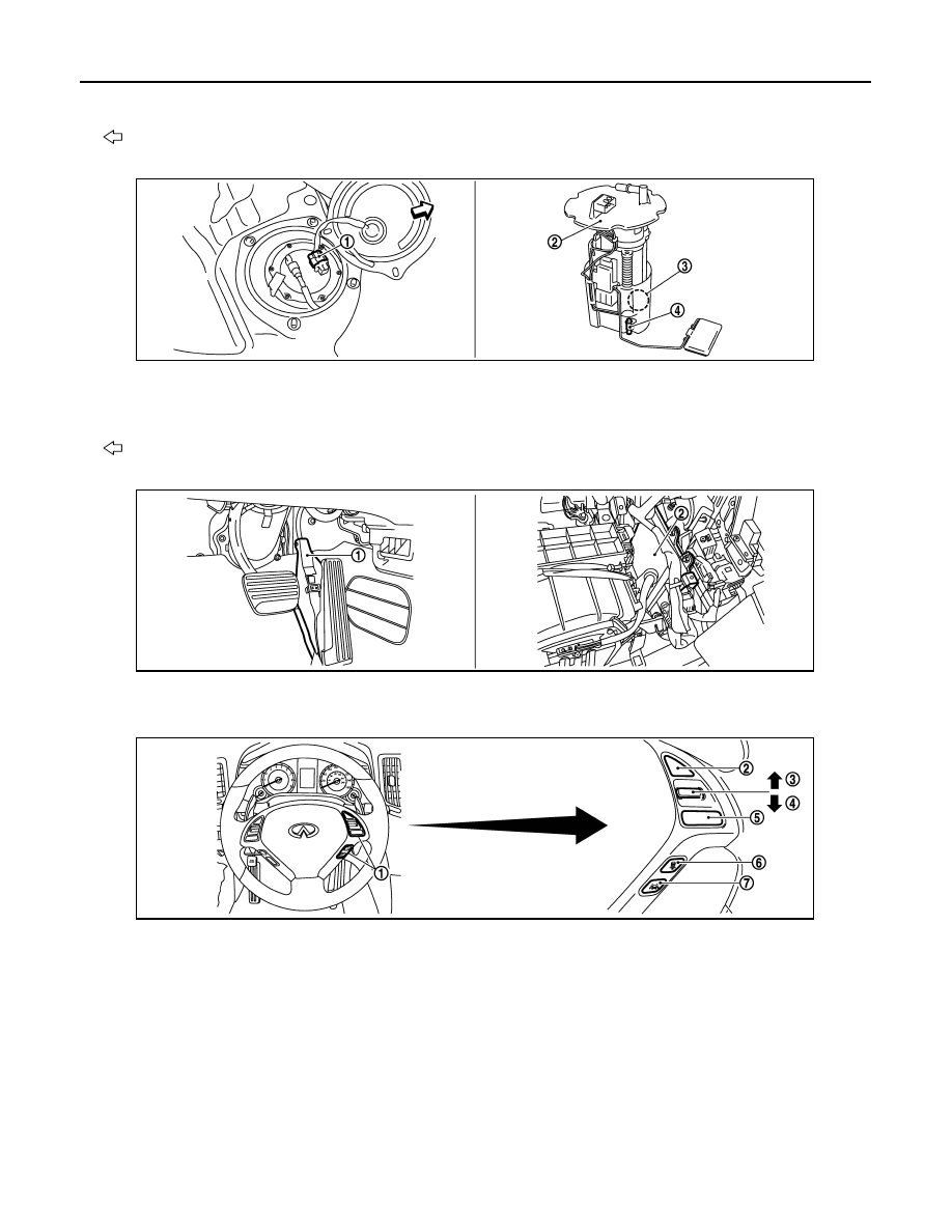
1.
Fuel level sensor unit and fuel pump
harness connector
2.
Fuel level sensor unit and fuel pump 3.
Fuel pressure regulator
4.
Fuel tank temperature sensor
: Vehicle front
1.
Accelerator pedal position sensor
2.
ECM
1.
ICC steering switch
2.
CANCEL switch
3.
RESUME/ACCELERATE switch
4.
SET/COAST switch
5.
MAIN switch
6.
DISTANCE switch
7.
LDP switch
JMBIA1182ZZ
JMBIA0015ZZ
JMBIA1308ZZ
ELECTRIC IGNITION SYSTEM
EC-47
< FUNCTION DIAGNOSIS >
[VQ35HR]
C
D
E
F
G
H
I
J
K
L
M
A
EC
N
P
O
Component Description
INFOID:0000000003133258
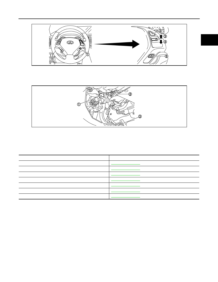
1.
ASCD steering switch
2.
CANCEL switch
3.
RESUME/ACCELERATE switch
4.
SET/COAST switch
5.
MAIN switch
1.
Stop lamp switch
2.
ASCD brake switch (ASCD models)
ICC brake switch (ICC models)
3.
Brake pedal
JMBIA0017ZZ
JMBIA0312ZZ
Component
Reference
Accelerator pedal position sensor
Camshaft position sensor (PHASE)
Crankshaft position sensor (POS)
Engine coolant temperature sensor
Knock sensor
Mass air flow sensor
Throttle position sensor
EC-48
< FUNCTION DIAGNOSIS >
[VQ35HR]
AIR CONDITIONING CUT CONTROL
AIR CONDITIONING CUT CONTROL
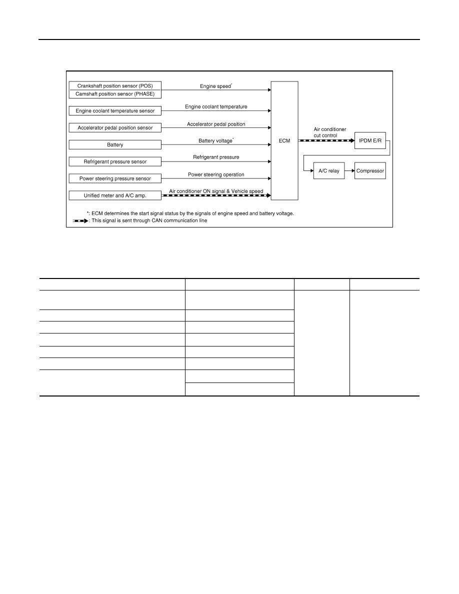
System Diagram
INFOID:0000000003133259
System Description
INFOID:0000000003133260
INPUT/OUTPUT SIGNAL CHART
*1: This signal is sent to the ECM through CAN communication line.
*2: ECM determines the start signal status by the signals of engine speed and battery voltage.
SYSTEM DESCRIPTION
This system improves engine operation when the air conditioner is used.
Under the following conditions, the air conditioner is turned off.
• When the accelerator pedal is fully depressed.
• When cranking the engine.
• At high engine speeds.
• When the engine coolant temperature becomes excessively high.
• When operating power steering during low engine speed or low vehicle speed.
• When engine speed is excessively low.
• When refrigerant pressure is excessively low or high.
JMBIA0073GB
Sensor
Input Signal to ECM
ECM function
Actuator
Crankshaft position sensor (POS)
Camshaft position sensor (PHASE)
Engine speed*
2
Air conditioner
cut control
IPDM E/R
↓
A/C relay
↓
Compressor
Engine coolant temperature sensor
Engine coolant temperature
Accelerator pedal position sensor
Accelerator pedal position
Battery
Battery voltage*
2
Refrigerant pressure sensor
Refrigerant pressure
Power steering pressure sensor
Power steering operation
Unified meter and A/C amp.
Air conditioner ON signal*
1
Vehicle speed*
1
AIR CONDITIONING CUT CONTROL
EC-49
< FUNCTION DIAGNOSIS >
[VQ35HR]
C
D
E
F
G
H
I
J
K
L
M
A
EC
N
P
O
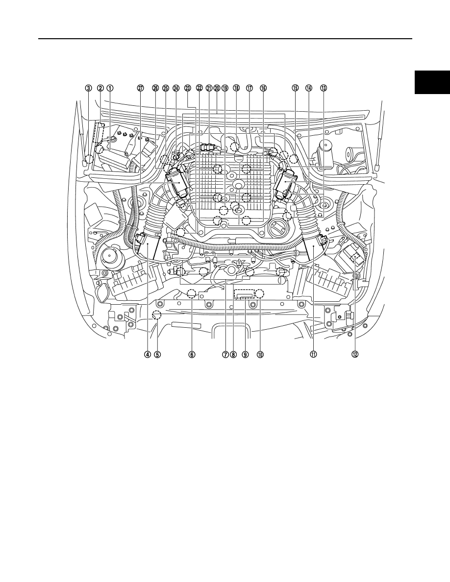
Component Parts Location
INFOID:0000000003738633
1.
Battery current sensor
2.
IPDM E/R
3.
Cooling fan relay
4.
Mass air flow sensor (with intake air
temperature sensor) (bank 1)
5.
Refrigerant pressure sensor
6.
Cooling fan motor-2
7.
Intake valve timing control solenoid
valve
8.
Exhaust valve timing control magnet
retarder
9.
Cooling fan control module
10. Cooling fan motor-1
11.
Mass air flow sensor (with intake air
temperature sensor) (bank 2)
12. ICC brake hold relay (ICC models)
13. Ignition coil (with power transistor)
and spark plug (bank 2)
14. Electric throttle control actuator
(bank 2)
15. A/F sensor 1 (bank 2)
16. Fuel injector (bank 2)
17. Camshaft position sensor (PHASE)
18. Engine coolant temperature sensor
19. Knock sensor
20. Exhaust valve timing control position
sensor
21. EVAP canister purge volume control
solenoid valve
22. Fuel injector (bank 1)
23. Ignition coil (with power transistor)
and spark plug (bank 1)
24. EVAP service port
25. A/F sensor 1 (bank 1)
26. Crankshaft position sensor (POS)
27. Electric throttle control actuator
(bank 1)
JMBIA0002ZZ
Нет комментариевНе стесняйтесь поделиться с нами вашим ценным мнением.
Текст