Infiniti EX35. Manual — part 1213
PWO-4
< PRECAUTION >
PRECAUTIONS
PRECAUTION
PRECAUTIONS
Precaution for Supplemental Restraint System (SRS) "AIR BAG" and "SEAT BELT
PRE-TENSIONER"
INFOID:0000000003516017
The Supplemental Restraint System such as “AIR BAG” and “SEAT BELT PRE-TENSIONER”, used along
with a front seat belt, helps to reduce the risk or severity of injury to the driver and front passenger for certain
types of collision. This system includes seat belt switch inputs and dual stage front air bag modules. The SRS
system uses the seat belt switches to determine the front air bag deployment, and may only deploy one front
air bag, depending on the severity of a collision and whether the front occupants are belted or unbelted.
Information necessary to service the system safely is included in the “SRS AIRBAG” and “SEAT BELT” of this
Service Manual.
WARNING:
• To avoid rendering the SRS inoperative, which could increase the risk of personal injury or death in
the event of a collision which would result in air bag inflation, all maintenance must be performed by
an authorized NISSAN/INFINITI dealer.
• Improper maintenance, including incorrect removal and installation of the SRS, can lead to personal
injury caused by unintentional activation of the system. For removal of Spiral Cable and Air Bag
Module, see the “SRS AIRBAG”.
• Do not use electrical test equipment on any circuit related to the SRS unless instructed to in this
Service Manual. SRS wiring harnesses can be identified by yellow and/or orange harnesses or har-
ness connectors.
PWO
POWER SOCKET
PWO-5
< ON-VEHICLE REPAIR >
C
D
E
F
G
H
I
J
K
L
B
A
O
P
N
ON-VEHICLE REPAIR
POWER SOCKET
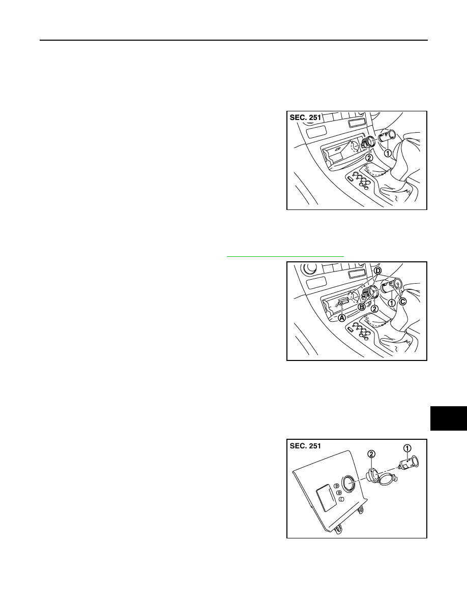
FRONT POWER SOCKET
FRONT POWER SOCKET : Exploded View
INFOID:0000000003523693
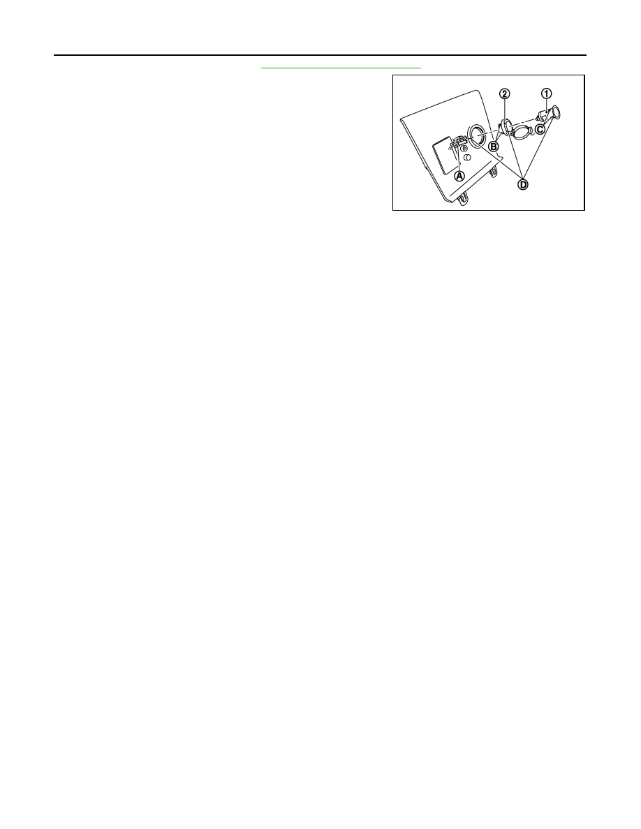
FRONT POWER SOCKET : Removal and Installation
INFOID:0000000003523694
REMOVAL
1.
Remove the console finisher assembly. Refer to
IP-22, "Removal and Installation"
2.
Disconnect the power socket connector (A).
3.
Pull out the inner socket (1) by pushing the ring pawl (B) from
the inner socket hole (square) (C).
4.
Remove the ring (2) from the console finisher assembly while
pressing pawls.
INSTALLATION
Install in the reverse order of removal.
NOTE:
Align the inner socket, the ring and the console finisher assembly cut out.
CONSOLE POWER SOCKET
CONSOLE POWER SOCKET : Exploded View
INFOID:0000000003131869
CONSOLE POWER SOCKET : Removal and Installation
INFOID:0000000003131870
REMOVAL
1
: Inner socket
2
: Ring
JPMIA0920ZZ
D
: Cut out
JPMIA0921ZZ
1
: Inner socket
2
: Ring
JPMIA0893ZZ
PWO-6
< ON-VEHICLE REPAIR >
POWER SOCKET
1.
Remove the console finisher. Refer to
IP-22, "Removal and Installation"
.
2.
Disconnect the power socket connector (A).
3.
Pull out the inner socket (1) by pushing the ring pawl (B) from
the inner socket hole (square) (C).
4.
Remove the ring (2) from the console finisher while pressing
pawls.
INSTALLATION
Install in the reverse order of removal.
NOTE:
Align the inner socket, the ring and the console finisher cut out.
D
: Cut out
JPMIA0894ZZ
2008 EX35 – Engine
VQ35HR
PREPARATION
Make sure that the following parts are in order.
1. Battery
2. Ignition system
3. Engine oil and coolant levels (Oil filler cap, oil level, etc.)
4. Fuse
5. ECM harness connector
6. Vacuum hoses
7. Air intake system
8. Fuel pressure
9. Engine compression
10. Throttle valve
11. Evaporative emission canister purge control valve.
Note:
• On A/C equipped vehicles, turn A/C "Off" for testing.
• Transmission should be in "Park" or "Neutral".
• "CO" probe should be inserted into exhaust approximately 16 inches.
• Turn off headlamps, heater blower, rear defogger, etc.
• Front wheels pointed straight.
• Perform inspection with cooling fans "Off".
Нет комментариевНе стесняйтесь поделиться с нами вашим ценным мнением.
Текст