Infiniti EX35. Manual — part 1135
PCS
POWER DISTRIBUTION SYSTEM
PCS-41
< FUNCTION DIAGNOSIS >
[POWER DISTRIBUTION SYSTEM]
C
D
E
F
G
H
I
J
K
L
B
A
O
P
N
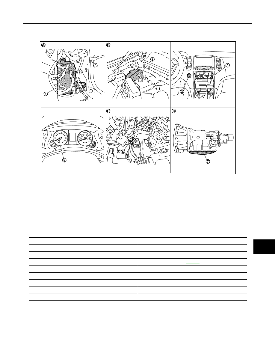
Component Parts Location
INFOID:0000000003586702
Component Description
INFOID:0000000003586703
JMMIA0011ZZ
1.
BCM M118, M119, M121, M122, M123 2.
IPDM E/R E5, E6, E7
3.
Push-button ignition switch M50
4.
Unified meter and A/C amp. M66, M67 5.
Combination meter (Key warning
lamp) M53
6.
Stop lamp switch E110
7.
TCM F151 (built into A/T assembly)
A.
Dash side lower (passenger side)
B.
Engine room dash panel (RH)
C.
Behind the instrument driver lower
panel
D.
A/T assembly
Component
Reference
IPDM E/R
Ignition relay (Built-in IPDM E/R)
Ignition relay (Built-in fuse block)
Accessory relay
Blower relay
Stop lamp switch
Park/neutral position switch
Push-button ignition switch

PCS-42
< FUNCTION DIAGNOSIS >
[POWER DISTRIBUTION SYSTEM]
DIAGNOSIS SYSTEM (BCM)
DIAGNOSIS SYSTEM (BCM)
COMMON ITEM
COMMON ITEM : CONSULT-III Function (BCM - COMMON ITEM)
INFOID:0000000003728540
APPLICATION ITEM
CONSULT-III performs the following functions via CAN communication with BCM.
SYSTEM APPLICATION
BCM can perform the following functions for each system.
NOTE:
It can perform the diagnosis modes except the following for all sub system selection items.
×
: Applicable item
NOTE:
*: This item is displayed, but is not used.
FREEZE FRAME DATA (FFD) AND IGN COUNTER
Freeze Frame Data
Diagnosis mode
Function Description
Work Support
Changes the setting for each system function.
Self Diagnostic Result
Displays the diagnosis results judged by BCM.
CAN Diag Support Monitor
Monitors the reception status of CAN communication viewed from BCM. Refer to CONSULT-III opera-
tion manual.
Data Monitor
The BCM input/output signals are displayed.
Active Test
The signals used to activate each device are forcibly supplied from BCM.
Ecu Identification
The BCM part number is displayed.
Configuration
• Read and save the vehicle specification.
• Write the vehicle specification when replacing BCM.
System
Sub system selection item
Diagnosis mode
Work Support
Data Monitor
Active Test
Door lock
DOOR LOCK
×
×
×
Rear window defogger
REAR DEFOGGER
×
×
Warning chime
BUZZER
×
×
Interior room lamp timer
INT LAMP
×
×
×
Exterior lamp
HEAD LAMP
×
×
×
Wiper and washer
WIPER
×
×
Turn signal and hazard warning lamps
FLASHER
×
×
×
—
AIR CONDITONER*
• Intelligent Key system
• Engine start system
INTELLIGENT KEY
×
×
×
Combination switch
COMB SW
×
Body control system
BCM
×
IVIS - NATS
IMMU
×
×
Interior room lamp battery saver
BATTERY SAVER
×
×
×
—
TRUNK*
×
×
Vehicle security system
THEFT ALM
×
×
×
RAP system
RETAINED PWR
×
Signal buffer system
SIGNAL BUFFER
×
×
TPMS
TPMS (AIR PRESSURE MONITOR)
×
×
×

PCS
DIAGNOSIS SYSTEM (BCM)
PCS-43
< FUNCTION DIAGNOSIS >
[POWER DISTRIBUTION SYSTEM]
C
D
E
F
G
H
I
J
K
L
B
A
O
P
N
The BCM records the following condition at the moment a particular DTC is detected.
• Vehicle Speed
• Odd Trip Meter
• Vehicle Condition (BCM detected condition)
IGN Counter
IGN counter indicates the number of times that ignition switch is turned ON after DTC is detected.
• The number is 0 when a malfunction is detected now.
• The number increases like 1
→
2
→
3...38
→
39 after returning to the normal condition whenever ignition
switch OFF
→
ON.
• The number is fixed to 39 until the self-diagnosis results are erased if it is over 39.
INTELLIGENT KEY
INTELLIGENT KEY : CONSULT-III Function (BCM - INTELLIGENT KEY)
INFOID:0000000003743933
BCM CONSULT-III FUNCTION
CONSULT-III performs the following functions via CAN communication with BCM.
WORK SUPPORT
CONSULT screen terms
Description
SLEEP>LOCK
While turning BCM status from low power consumption mode to normal mode (Power supply
position is “LOCK”)
SLEEP>OFF
While turning BCM status from low power consumption mode to normal mode (Power supply
position is “OFF”.)
LOCK>ACC
While turning power supply position from “LOCK” to “ACC”
ACC>ON
While turning power supply position from “ACC” to “IGN”
RUN>ACC
While turning power supply position from “RUN” to “ACC” (Vehicle is stopping and selector
lever is except P position.)
CRANK>RUN
While turning power supply position from “CRANKING” to “RUN” (From cranking up the en-
gine to run it)
RUN>URGENT
While turning power supply position from “RUN“ to “ACC” (Emergency stop operation)
ACC>OFF
While turning power supply position from “ACC” to “OFF”
OFF>LOCK
While turning power supply position from “OFF” to “LOCK”
OFF>ACC
While turning power supply position from “OFF” to “ACC”
ON>CRANK
While turning power supply position from “IGN” to “CRANKING”
OFF>SLEEP
While turning BCM status from normal mode (Power supply position is “OFF”.) to low power
consumption mode
LOCK>SLEEP
While turning BCM status from normal mode (Power supply position is “LOCK”.) to low pow-
er consumption mode
LOCK
Power supply position is “LOCK” (Ignition switch OFF with steering is locked.)
OFF
Power supply position is “OFF” (Ignition switch OFF with steering is unlocked.)
ACC
Power supply position is “ACC” (Ignition switch ACC)
ON
Power supply position is “IGN” (Ignition switch ON with engine stopped)
ENGINE RUN
Power supply position is “RUN” (Ignition switch ON with engine running)
CRANKING
Power supply position is “CRANKING” (At engine cranking)
Diagnosis mode
Function Description
WORK SUPPORT
Changes the setting for each system function.
SELF-DIAG RESULTS
Displays the diagnosis results judged by BCM.
DATA MONITOR
The BCM input/output signals are displayed.
ACTIVE TEST
The signals used to activate each device are forcibly supplied from BCM.

PCS-44
< FUNCTION DIAGNOSIS >
[POWER DISTRIBUTION SYSTEM]
DIAGNOSIS SYSTEM (BCM)
SELF-DIAG RESULT
DATA MONITOR
Monitor item
Description
REMO CONT ID CONFIR
It can be checked whether Intelligent Key ID code is registered or not in this mode.
AUTO LOCK SET
Auto door lock time can be changed in this mode.
• MODE 1: 1 minute
• MODE 2: 5 minutes
• MODE 3: 30 seconds
• MODE 4: 2 minutes
LOCK/UNLOCK BY I-KEY
Door lock/unlock function by door request switch (driver side, passenger side and back door) mode
can be changed to operate (ON) or not operate (OFF) in this mode.
ENGINE START BY I-KEY
Engine start function mode can be changed to operate (ON) or not operate (OFF) with this mode.
TRUNK/GLASS HATCH OPEN
Buzzer reminder function mode by back door request switch can be changed to operate (ON) or
not operate (OFF) with this mode.
PANIC ALARM SET
Panic alarm button pressing time on Intelligent Key remote control button can be selected from the
following with this mode.
• MODE 1: 0.5 sec.
• MODE 2: Non-operation
• MODE 3: 1.5 sec.
PW DOWN SET
Unlock button pressing time on Intelligent Key button can be selected from the following with this
mode.
• MODE 1: 3 sec.
• MODE 2: Non-operation
• MODE 3: 5 sec.
TRUNK OPEN DELAY
NOTE:
This item is displayed, but cannot be supported.
LO- BATT OF KEY FOB WARN
Intelligent Key low battery warning mode can be changed to operate (ON) or not operate (OFF)
with this mode.
ANTI KEY LOCK IN FUNCTI
Key reminder function mode can be changed to operate (ON) or not operate (OFF) with this mode.
HAZARD ANSWER BACK
Hazard reminder function mode can be selected from the following with this mode.
• LOCK ONLY: Door lock operation only
• UNLOCK ONLY: Door unlock operation only
• LOCK/UNLOCK: Lock/unlock operation
• OFF: Non-operation
ANS BACK I-KEY LOCK
Buzzer reminder function (lock operation) mode by door request switch (driver side and passenger
side) can be selected from the following with this mode.
• Horn chirp: Sound horn
• Buzzer: Sound Intelligent Key warning buzzer
• OFF: Non-operation
ANS BACK I-KEY UNLOCK
Buzzer reminder function (unlock operation) mode by door request switch can be changed to op-
erate (ON) or not operate (OFF) with this mode.
SHORT CRANKING OUTPUT
Starter motor can operate during the times below.
• 70 msec
• 100 msec
• 200 msec
INSIDE ANT DIAGNOSIS
This function allows inside key antenna self-diagnosis.
HORN WITH KEYLESS LOCK
Horn reminder function mode by Intelligent Key button can be changed to operate (ON) or not op-
erate (OFF) with this mode.
Monitor Item
Condition
REQ SW -DR
Indicates [ON/OFF] condition of door request switch (driver side).
REQ SW -AS
Indicates [ON/OFF] condition of door request switch (passenger side).
REQ SW -RR
NOTE:
This item is displayed, but cannot be monitored.
Нет комментариевНе стесняйтесь поделиться с нами вашим ценным мнением.
Текст