Infiniti EX35. Manual — part 517
DLN-18
< COMPONENT DIAGNOSIS >
[TRANSFER: ETX13B]
C1210 ECM
C1210 ECM
Description
INFOID:0000000003561167
Transmits the following signals via CAN communication to AWD control unit.
• Accelerator pedal position signal
• Engine speed signal
DTC Logic
INFOID:0000000003561168
DTC DETECTION LOGIC
DTC CONFIRMATION PROCEDURE
1.
DTC REPRODUCTION PROCEDURE
With CONSULT-III
1.
Start the engine. Drive the vehicle for a while.
2.
Perform AWD control unit self-diagnosis.
Is DTC “C1210” detected?
YES
>> Proceed to diagnosis procedure. Refer to
NO
>> INSPECTION END
Diagnosis Procedure
INFOID:0000000003561169
1.
PERFORM ECM SELF-DIAGNOSIS
With CONSULT-III
Perform ECM self-diagnosis.
Is any DTC detected?
YES
>> Check the DTC.
NO
>> GO TO 2.
2.
PERFORM SELF-DIAGNOSIS
With CONSULT-III
1.
Erase AWD control unit self-diagnostic results.
2.
Turn the ignition switch OFF.
3.
Start the engine. Drive the vehicle for a while.
4.
Make sure that malfunction indicator lamp (MIL) turns OFF.
5.
Stop the vehicle. Perform AWD control unit self-diagnosis.
Is DTC “C1210” detected?
YES
>> Replace AWD control unit. Refer to
.
NO
>> Check AWD control unit pin terminals for damage or loose connection with harness connector. If
any items are damaged, repair or replace damaged parts.
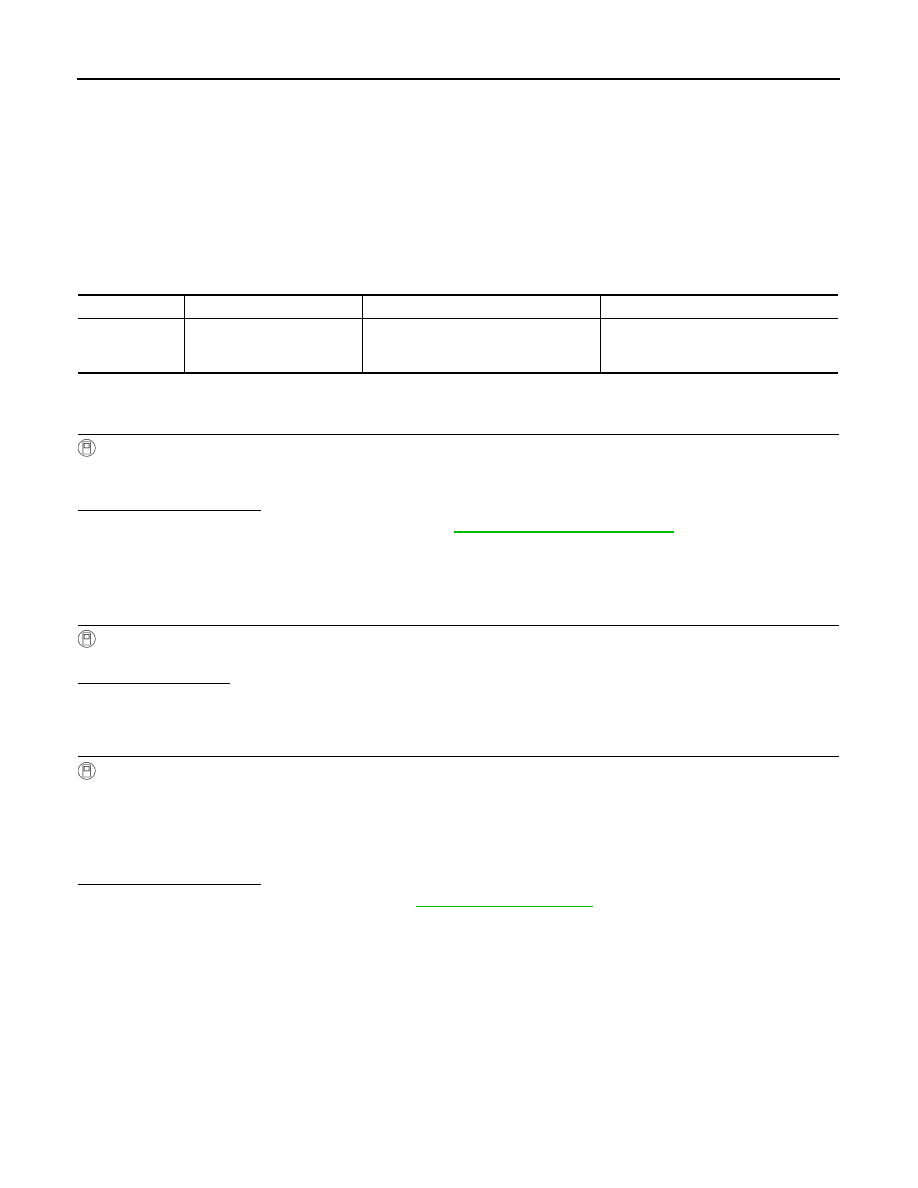
DTC
Display item
Malfunction detected condition
Possible cause
C1210
ENGINE SIGNAL 1
Malfunction has been detected from
ECM.
Malfunction of engine control system
• Accelerator pedal position signal error
• Engine speed signal error
U1000 CAN COMM CIRCUIT
DLN-19
< COMPONENT DIAGNOSIS >
[TRANSFER: ETX13B]
C
E
F
G
H
I
J
K
L
M
A
B
DLN
N
O
P
U1000 CAN COMM CIRCUIT
Description
INFOID:0000000003561170
CAN (Controller Area Network) is a serial communication line for real time application. It is an on-vehicle mul-
tiplex communication line with high data communication speed and excellent error detection ability. Many elec-
tronic control units are equipped onto a vehicle, and each control unit shares information and links with other
control units during operation (not independent). In CAN communication, control units are connected with 2
communication lines (CAN-H line, CAN-L line) allowing a high rate of information transmission with less wiring.
Each control unit transmits/receives data but selectively reads required data only.
DTC Logic
INFOID:0000000003561171
DTC DETECTION LOGIC
DTC CONFIRMATION PROCEDURE
1.
DTC REPRODUCTION PROCEDURE
With CONSULT-III
1.
Turn the ignition switch OFF to ON.
2.
Perform AWD control unit self-diagnosis.
Is DTC “U1000” detected?
YES
>> Proceed to diagnosis procedure. Refer to
NO
>> INSPECTION END
Diagnosis Procedure
INFOID:0000000003561172
1.
PERFORM SELF-DIAGNOSIS
With CONSULT-III
Perform AWD control unit self-diagnosis.
Is DTC “U1000” detected?
YES
>> CAN specification chart. Refer to
LAN-18, "Trouble Diagnosis Flow Chart"
NO
>> INSPECTION END
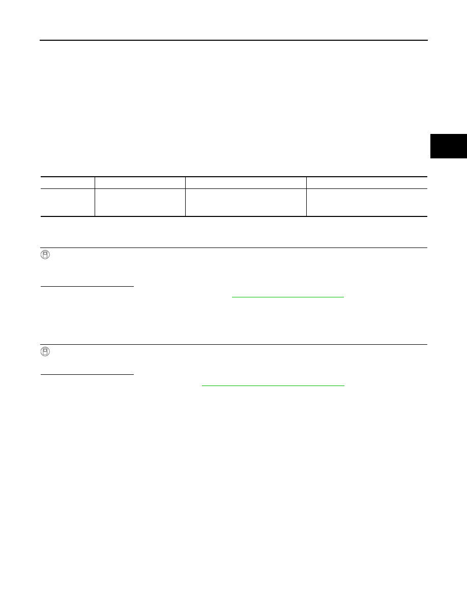
DTC
Display item
Malfunction detected condition
Possible cause
U1000
CAN COMM CIRCUIT
AWD control unit is not transmitting/re-
ceiving CAN communication signal for 2
seconds or more.
• CAN communication error
• Malfunction of AWD control unit
DLN-20
< COMPONENT DIAGNOSIS >
[TRANSFER: ETX13B]
U1010 CONTROL UNIT (CAN)
U1010 CONTROL UNIT (CAN)
Description
INFOID:0000000003561173
CAN (Controller Area Network) is a serial communication line for real time application. It is an on-vehicle mul-
tiplex communication line with high data communication speed and excellent error detection ability. Many elec-
tronic control units are equipped onto a vehicle, and each control unit shares information and links with other
control units during operation (not independent). In CAN communication, control units are connected with 2
communication lines (CAN-H line, CAN-L line) allowing a high rate of information transmission with less wiring.
Each control unit transmits/receives data but selectively reads required data only.
DTC Logic
INFOID:0000000003561174
DTC DETECTION LOGIC
DTC CONFIRMATION PROCEDURE
1.
DTC REPRODUCTION PROCEDURE
With CONSULT-III
1.
Turn the ignition switch OFF to ON.
2.
Perform AWD control unit self-diagnosis.
Is DTC “U1010” detected?
YES
>> Proceed to diagnosis procedure. Refer to
NO
>> INSPECTION END
Diagnosis Procedure
INFOID:0000000003561175
1.
CHECK AWD CONTROL UNIT
Check AWD control unit harness connector for disconnection and deformation.
Is the inspection result normal?
YES
>> Replace AWD control unit. Refer to
NO
>> Repair or replace damaged parts.
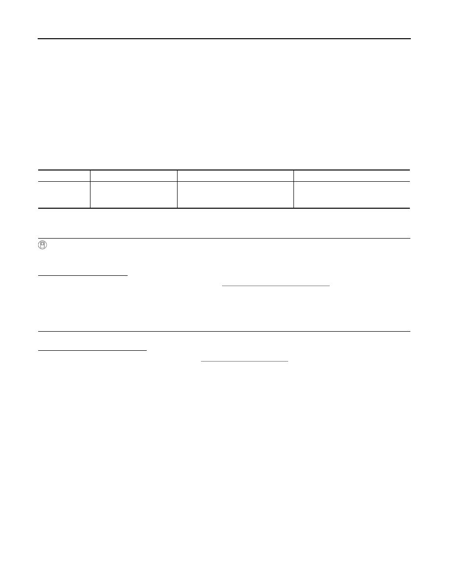
DTC
Display item
Malfunction detected condition
Possible cause
U1010
CONTROL UNIT (CAN)
Detecting error during the initial diagno-
sis of CAN controller of AWD control
unit.
Malfunction of AWD control unit

POWER SUPPLY AND GROUND CIRCUIT
DLN-21
< COMPONENT DIAGNOSIS >
[TRANSFER: ETX13B]
C
E
F
G
H
I
J
K
L
M
A
B
DLN
N
O
P
POWER SUPPLY AND GROUND CIRCUIT
Description
INFOID:0000000003773513
Supplies power to AWD control unit.
Diagnosis Procedure
INFOID:0000000003773514
1.
CHECK AWD CONTROL UNIT POWER SUPPLY (1)
1.
Turn the ignition switch OFF.
2.
Disconnect AWD control unit harness connector.
3.
Check the voltage between AWD control unit harness connector and ground.
4.
Turn the ignition switch ON.
CAUTION:
Never start the engine.
5.
Check the voltage between AWD control unit harness connector and ground.
Is the inspection result normal?
YES
>> GO TO 3.
NO
>> GO TO 2.
2.
CHECK AWD CONTROL UNIT POWER SUPPLY (2)
1.
Turn the ignition switch OFF.
2.
Check the 10A fuse (#45).
3.
Disconnect IPDM E/R harness connector E5.
4.
Check the harness for open or short between AWD control unit harness connector No.7 terminal and
IPDM E/R harness connector No.25 terminal.
Is the inspection result normal?
YES
>> Perform the trouble diagnosis for ignition power supply circuit. Refer to
NO
>> Repair or replace damaged parts.
3.
CHECK AWD SOLENOID POWER SUPPLY (1)
1.
Turn the ignition switch OFF.
2.
Disconnect AWD solenoid harness connector.
3.
Check the voltage between AWD control unit harness connector and ground.
4.
Turn the ignition switch ON.
CAUTION:
Never start the engine.
5.
Check the voltage between AWD control unit harness connector and ground.
AWD control unit
—
Voltage (Approx.)
Connector
Terminal
F108
7
Ground
0 V
AWD control unit
—
Voltage
Connector
Terminal
F108
7
Ground
Battery voltage
AWD control unit
—
Voltage
Connector
Terminal
F108
9
Ground
Battery voltage
Нет комментариевНе стесняйтесь поделиться с нами вашим ценным мнением.
Текст