Infiniti EX35. Manual — part 1043
LAN
CAN COMMUNICATION CIRCUIT
LAN-231
< COMPONENT DIAGNOSIS >
[CAN SYSTEM (TYPE 9)]
C
D
E
F
G
H
I
J
K
L
B
A
O
P
N
Inspection result
Reproduced>>GO TO 6.
Non-reproduced>>Start the diagnosis again. Follow the trouble diagnosis procedure when past error is
detected.
6.
CHECK UNIT REPRODUCTION
Perform the reproduction test as per the following procedure for each unit.
1.
Turn the ignition switch OFF.
2.
Disconnect the battery cable from the negative terminal.
3.
Disconnect one of the unit connectors of CAN communication system.
NOTE:
ECM and IPDM E/R have a termination circuit. Check other units first.
4.
Connect the battery cable to the negative terminal. Check if the symptoms described in the “Symptom
(Results from interview with customer)” are reproduced.
NOTE:
Although unit-related error symptoms occur, do not confuse them with other symptoms.
Inspection result
Reproduced>>Connect the connector. Check other units as per the above procedure.
Non-reproduced>>Replace the unit whose connector was disconnected.

LAN-232
< COMPONENT DIAGNOSIS >
[CAN SYSTEM (TYPE 10)]
MAIN LINE BETWEEN AV AND DLC CIRCUIT
COMPONENT DIAGNOSIS
MAIN LINE BETWEEN AV AND DLC CIRCUIT
Diagnosis Procedure
INFOID:0000000003515797
INSPECTION PROCEDURE
1.
CHECK HARNESS CONTINUITY (OPEN CIRCUIT)
1.
Turn the ignition switch OFF.
2.
Disconnect the battery cable from the negative terminal.
3.
Disconnect the following harness connectors.
-
ECM
-
AV control unit
4.
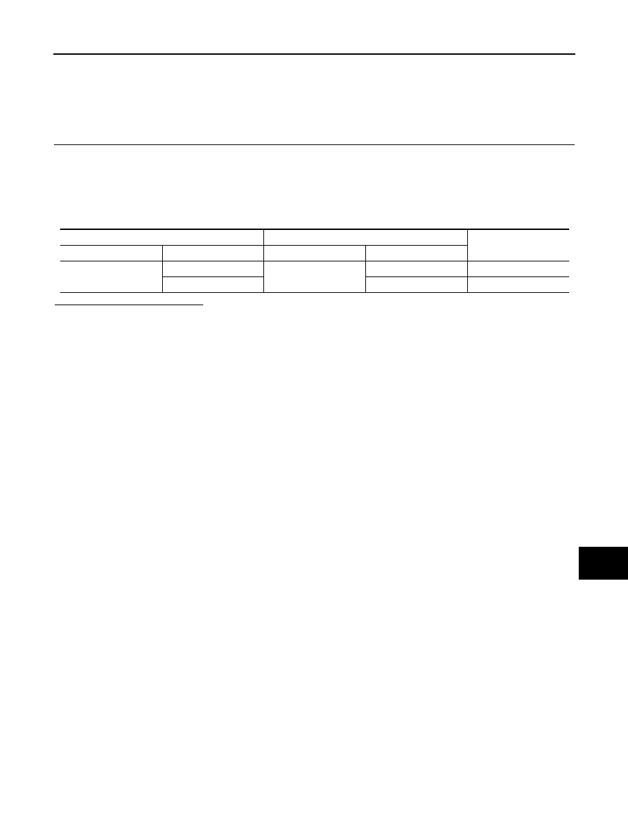
Check the continuity between the AV control unit harness connector and the data link connector.
-
Models with NAVI
-
Models without NAVI
Is the inspection result normal?
YES (Present error)>>Check CAN system type decision again.
YES (Past error)>>Error was detected in the main line between the AV control unit and the data link connec-
tor.
NO
>> Repair the main line between the AV control unit and the data link connector.
AV control unit harness connector
Data link connector
Continuity
Connector No.
Terminal No.
Connector No.
Terminal No.
M87
52
M24
6
Existed
53
14
Existed
AV control unit harness connector
Data link connector
Continuity
Connector No.
Terminal No.
Connector No.
Terminal No.
M85
86
M24
6
Existed
87
14
Existed
LAN
MAIN LINE BETWEEN DLC AND TCM CIRCUIT
LAN-233
< COMPONENT DIAGNOSIS >
[CAN SYSTEM (TYPE 10)]
C
D
E
F
G
H
I
J
K
L
B
A
O
P
N
MAIN LINE BETWEEN DLC AND TCM CIRCUIT
Diagnosis Procedure
INFOID:0000000003515799
INSPECTION PROCEDURE
1.
CHECK HARNESS CONTINUITY (OPEN CIRCUIT)
1.
Turn the ignition switch OFF.
2.
Disconnect the battery cable from the negative terminal.
3.
Disconnect the following harness connectors.
-
ECM
-
Harness connectors M116 and F103
4.
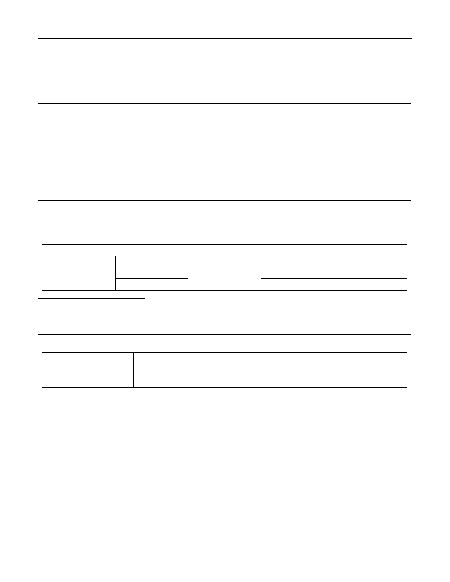
Check the continuity between the data link connector and the harness connector.
Is the inspection result normal?
YES (Present error)>>Check CAN system type decision again.
YES (Past error)>>Error was detected in the main line between the data link connector and the TCM.
NO
>> Repair the main line between the data link connector and the harness connector M116.
Data link connector
Harness connector
Continuity
Connector No.
Terminal No.
Connector No.
Terminal No.
M24
6
M116
44
Existed
14
43
Existed
LAN-234
< COMPONENT DIAGNOSIS >
[CAN SYSTEM (TYPE 10)]
MAIN LINE BETWEEN TCM AND ADP CIRCUIT
MAIN LINE BETWEEN TCM AND ADP CIRCUIT
Diagnosis Procedure
INFOID:0000000003515803
INSPECTION PROCEDURE
1.
CHECK CONNECTOR
1.
Turn the ignition switch OFF.
2.
Disconnect the battery cable from the negative terminal.
3.
Check the following terminals and connectors for damage, bend and loose connection (connector side
and harness side).
-
Harness connector M7
-
Harness connector B1
Is the inspection result normal?
YES
>> GO TO 2.
NO
>> Repair the terminal and connector.
2.
CHECK HARNESS CONTINUITY (OPEN CIRCUIT)
1.
Disconnect the following harness connectors.
-
Harness connectors F103 and M116
-
Harness connectors M7 and B1
2.
Check the continuity between the harness connectors.
Is the inspection result normal?
YES
>> GO TO 3.
NO
>> Repair the main line between the harness connectors M116 and M7.
3.
CHECK HARNESS CONTINUITY (OPEN CIRCUIT)
Check the continuity between the harness connector terminals.
Is the inspection result normal?
YES (Present error)>>Check CAN system type decision again.
YES (Past error)>>Error was detected in the main line between the TCM and the driver seat control unit.
NO
>> Repair the main line between the harness connector B1 and the driver seat control unit.
Harness connector
Harness connector
Continuity
Connector No.
Terminal No.
Connector No.
Terminal No.
M116
44
M7
34
Existed
43
35
Existed
Connector No.
Terminal No.
Continuity
B1
34
36
Existed
35
37
Existed
Нет комментариевНе стесняйтесь поделиться с нами вашим ценным мнением.
Текст