Infiniti EX35. Manual — part 58
AV
DIAGNOSIS AND REPAIR WORKFLOW
AV-13
< BASIC INSPECTION >
[BASE AUDIO WITHOUT NAVIGATION]
C
D
E
F
G
H
I
J
K
L
M
B
A
O
P
BASIC INSPECTION
DIAGNOSIS AND REPAIR WORKFLOW
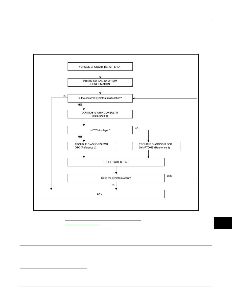
Work Flow
INFOID:0000000003508362
OVERALL SEQUENCE
• Reference 1··· Refer to
AV-37, "CONSULT-III Function (MULTI AV)"
.
• Reference 2··· Refer to
• Reference 3··· Refer to
DETAILED FLOW
1.
INTERVIEW AND SYMPTOM CONFIRMATION
Check the malfunction symptoms by performing the following items.
• Interview the customer to obtain the malfunction information (conditions and environment when the malfunc-
tion occurred).
• Check the symptom.
Is the occurred symptom malfunction?
YES
>> GO TO 2.
NO
>> INSPECTION END
2.
DIAGNOSIS WITH CONSULT-III
JSNIA0732GB

AV-14
< BASIC INSPECTION >
[BASE AUDIO WITHOUT NAVIGATION]
DIAGNOSIS AND REPAIR WORKFLOW
1.
Connect CONSULT-III and perform a self-diagnosis for “MULTI AV”. Refer to
NOTE:
Skip to step 4 of the diagnosis procedure if “MULTI AV” is not displayed.
2.
Check if any DTC is displayed in the self-diagnosis results.
Is DTC displayed?
YES
>> GO TO 3.
NO
>> GO TO 4.
3.
TROUBLE DIAGNOSIS FOR DTC
1.
Check the DTC indicated in the self-diagnosis results.
2.
Perform the relevant diagnosis referring to the DTC Index. Refer to
.
>> GO TO 5.
4.
TROUBLE DIAGNOSIS FOR SYMPTOMS
Perform the relevant diagnosis referring to the diagnosis chart by symptom. Refer to
.
>> GO TO 5.
5.
ERROR PART REPAIR
1.
Repair or replace the identified malfunctioning parts.
2.
Perform a self-diagnosis for “MULTI AV” with CONSULT-III.
NOTE:
Erase the stored self-diagnosis results after repairing or replacing the relevant components if any DTC
has been indicated in the self-diagnosis results.
3.
Check that the symptom does not occur.
Does the symptom occur?
YES
>> GO TO 1.
NO
>> INSPECTION END

AV
INSPECTION AND ADJUSTMENT
AV-15
< BASIC INSPECTION >
[BASE AUDIO WITHOUT NAVIGATION]
C
D
E
F
G
H
I
J
K
L
M
B
A
O
P
INSPECTION AND ADJUSTMENT
ADDITIONAL SERVICE WHEN REMOVING BATTERY NEGATIVE TERMINAL
ADDITIONAL SERVICE WHEN REMOVING BATTERY NEGATIVE TERMINAL : De-
scription
INFOID:0000000003569901
WITH REAR VIEW MONITOR
Always correct the center position of the predicted course line after disconnecting the battery negative termi-
nal.
ADDITIONAL SERVICE WHEN REMOVING BATTERY NEGATIVE TERMINAL : Spe-
cial Repair Requirement
INFOID:0000000003569902
1.
CORRECTION OF CENTER POSITION OF PREDICTED COURSE LINE
Refer to the following for details.
>> Refer to
AV-15, "PREDICTED COURSE LINE CENTER POSITION ADJUSTMENT : Special
.
ADDITIONAL SERVICE WHEN REPLACING CONTROL UNIT
ADDITIONAL SERVICE WHEN REPLACING CONTROL UNIT : Description
INFOID:0000000003569903
When camera control unit is replaced, the center position of predicted course line shall be corrected.
ADDITIONAL SERVICE WHEN REPLACING CONTROL UNIT : Special Repair Re-
quirement
INFOID:0000000003569904
1.
CORRECTION OF CENTER POSITION OF PREDICTED COURSE LINE
Refer to the following for details.
>> Refer to
AV-15, "PREDICTED COURSE LINE CENTER POSITION ADJUSTMENT : Special
.
PREDICTED COURSE LINE CENTER POSITION ADJUSTMENT
PREDICTED COURSE LINE CENTER POSITION ADJUSTMENT : Description
INFOID:0000000003569905
Adjust the center position of the predicted course line of the rear view monitor if it is shifted.
PREDICTED COURSE LINE CENTER POSITION ADJUSTMENT : Special Repair
Requirement
INFOID:0000000003569906
1.
STEERING OPERATION
Steer the steering wheel to the leftmost and rightmost ends.
>> GO TO 2
2.
DRIVING
Drive the vehicle straight ahead 100 m (328.1 ft) or more at a speed of 30 km/h (18.6 MPH) or more.
>> END
AV-16
< FUNCTION DIAGNOSIS >
[BASE AUDIO WITHOUT NAVIGATION]
MULTI AV SYSTEM
FUNCTION DIAGNOSIS
MULTI AV SYSTEM
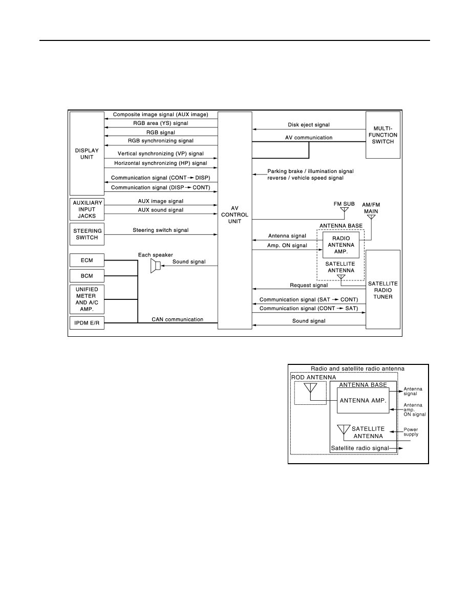
System Diagram
INFOID:0000000003508363
WITHOUT REAR VIEW MONITOR
NOTE:
• The name MULTIFUNCTION SWITCH indicates the integration of PRESET SWITCH and MULTIFUNCTION
SWITCH virtually.
• A radio antenna base integrated with radio antenna and satellite
radio antenna is adopted.
JSNIA0690GB
JSNIA1062GB
Нет комментариевНе стесняйтесь поделиться с нами вашим ценным мнением.
Текст