Infiniti EX35. Manual — part 160
AV
SATELLITE RADIO TUNER
AV-421
< ON-VEHICLE REPAIR >
[BOSE AUDIO WITHOUT NAVIGATION]
C
D
E
F
G
H
I
J
K
L
M
B
A
O
P
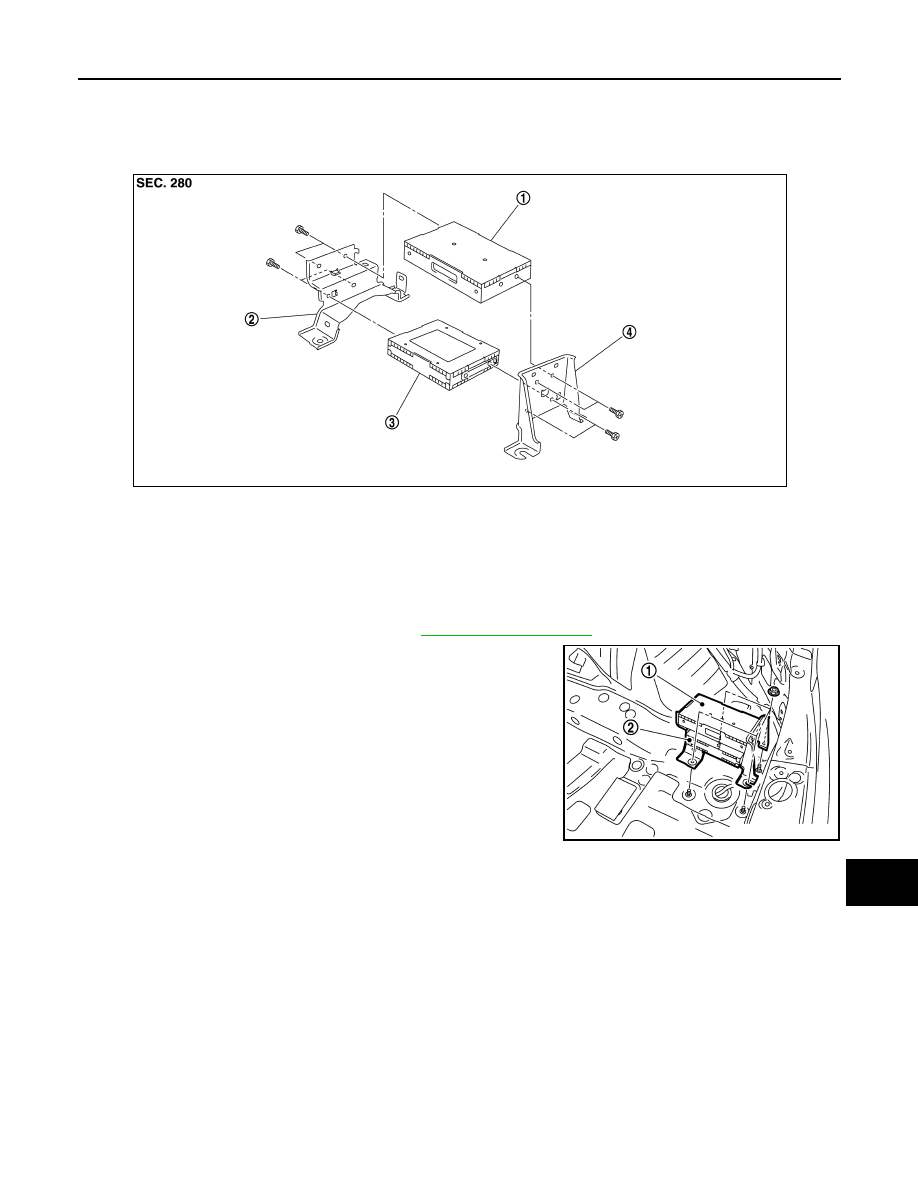
SATELLITE RADIO TUNER
Exploded View
INFOID:0000000003508772
Removal and Installation
INFOID:0000000003508773
REMOVAL
1.
Remove luggage floor spacer (RH). Refer to
2.
Remove nuts, and then remove TEL adapter unit (1) and satel-
lite radio tuner (2).
INSTALLATION
Install in the reverse order of removal.
1.
TEL adapter unit
2.
Bracket (front)
3.
Satellite radio tuner
4.
Bracket (rear)
JPNIA0495ZZ
JPNIA0890ZZ
AV-422
< ON-VEHICLE REPAIR >
[BOSE AUDIO WITHOUT NAVIGATION]
ANTENNA BASE
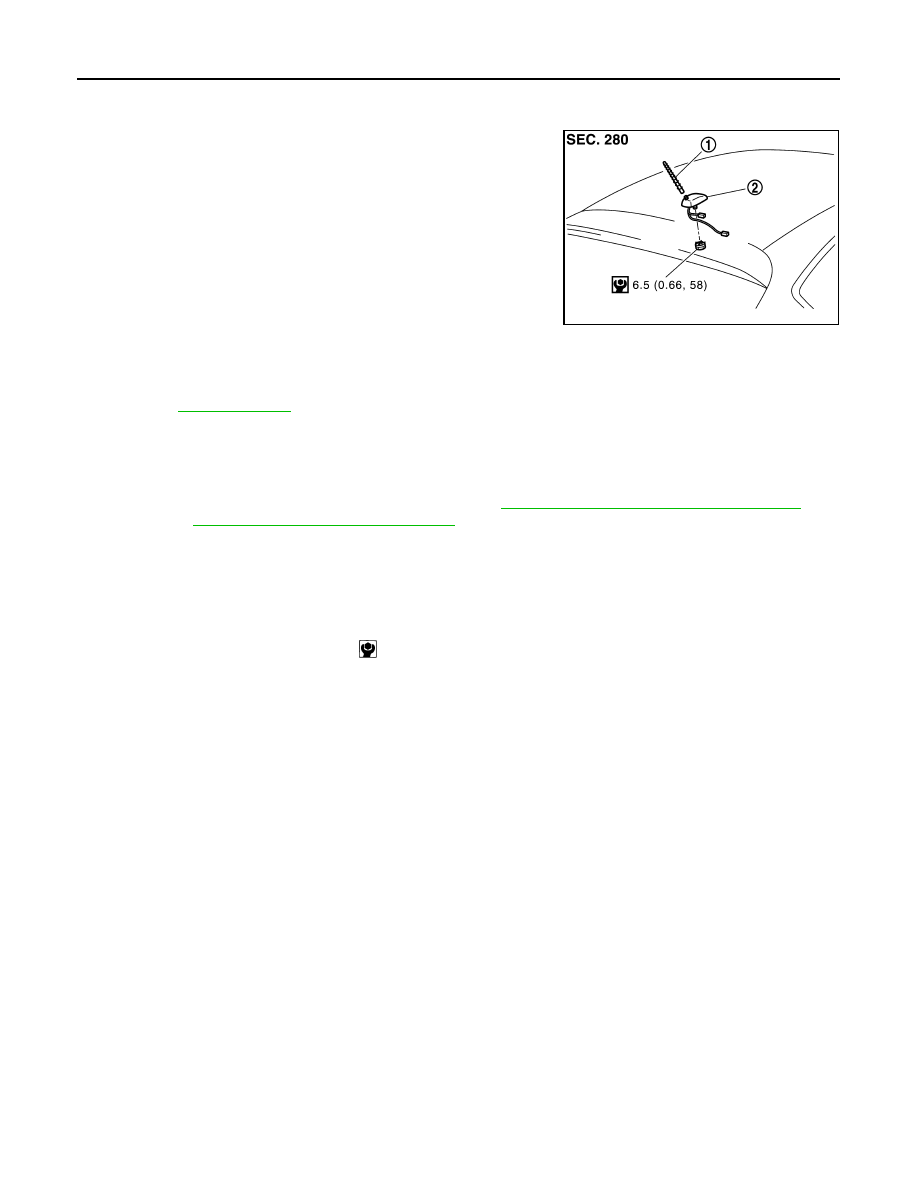
ANTENNA BASE
Exploded View
INFOID:0000000003508774
Removal and Installation
INFOID:0000000003569877
REMOVAL
1.
Remove headlining (rear). Keep a service area. Refer to
INT-26, "NORMAL ROOF : Exploded View"
mal roof) or
INT-30, "SUNROOF : Exploded View"
2.
Remove antenna base mounting nut.
3.
Remove antenna base.
INSTALLATION
Installation is the reverse order of removal.
CAUTION:
Be careful about tightening torque. Antenna sensitivity becomes poor, and when it is excessive, roof
panel may be deformed, when roof antenna mounting nut tightening torque is loose.
JPNIA0880GB
1.
Antenna rod
2.
Antenna base
for symbols in the figure.
Antenna base mounting nut
: 6.5 N·m (0.66 kg-m, 58 in-lb)
AV
MULTIFUNCTION SWITCH
AV-423
< ON-VEHICLE REPAIR >
[BOSE AUDIO WITHOUT NAVIGATION]
C
D
E
F
G
H
I
J
K
L
M
B
A
O
P
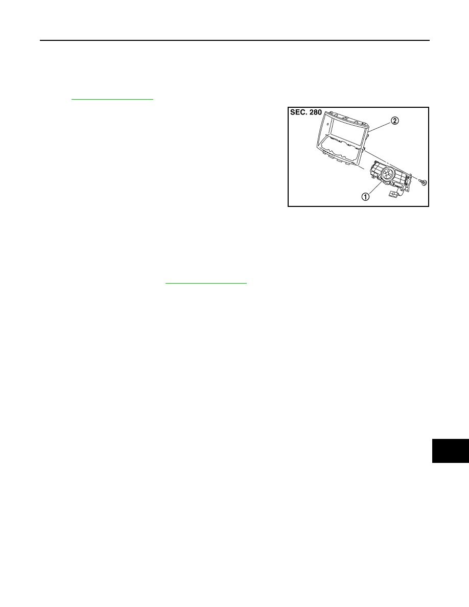
MULTIFUNCTION SWITCH
Exploded View
INFOID:0000000003573761
REMOVAL
.
DISASSEMBLY
Removal and Installation
INFOID:0000000003573762
REMOVAL
1.
Remove cluster lid D. Refer to
.
2.
Remove multifunction switch mounting screws.
3.
Remove multifunction switch.
INSTALLATION
Installation is the reverse order of removal.
JPNIA0881ZZ
1.
Multifunction switch
2.
Cluster lid D
AV-424
< ON-VEHICLE REPAIR >
[BOSE AUDIO WITHOUT NAVIGATION]
PRESET SWITCH
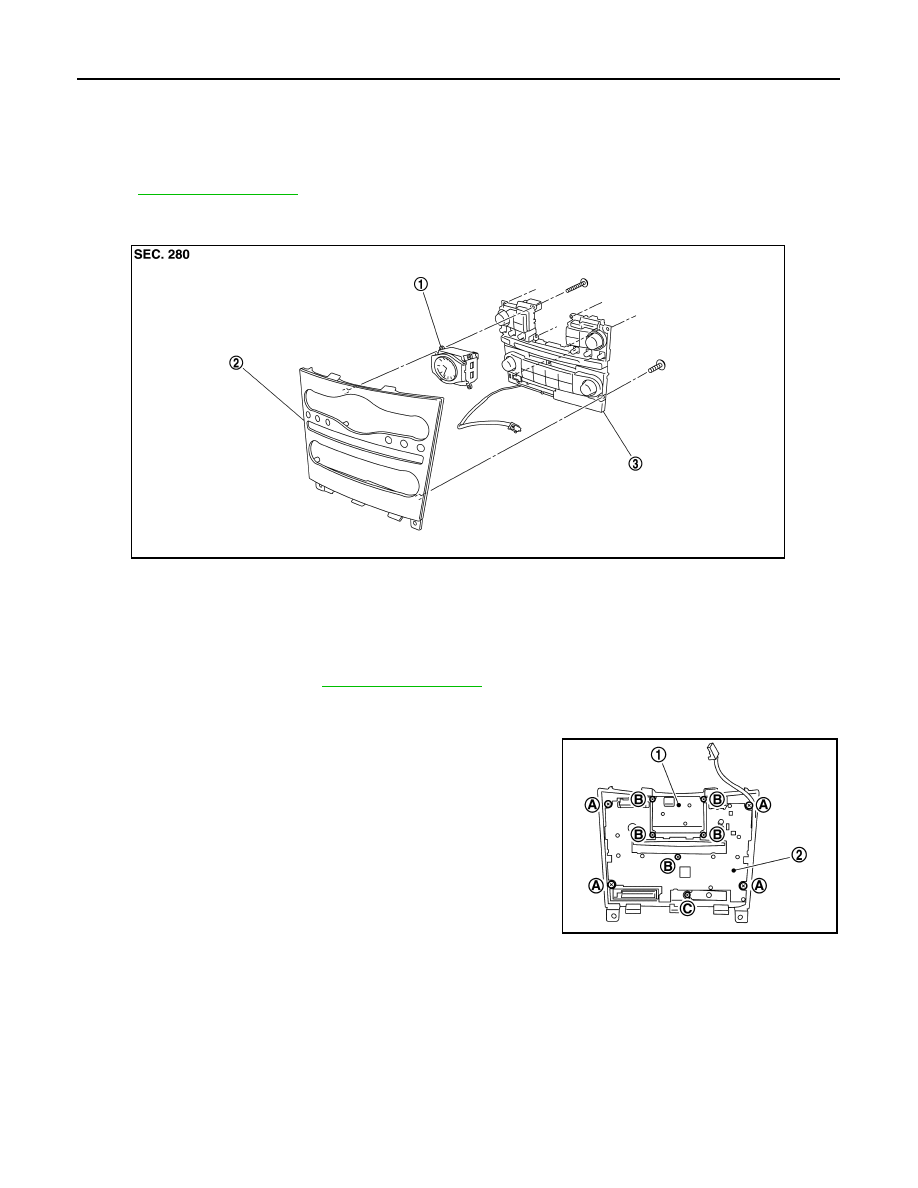
PRESET SWITCH
Exploded View
INFOID:0000000003573763
REMOVAL
.
DISASSEMBLY
Removal and Installation
INFOID:0000000003573764
REMOVAL
1.
Remove cluster lid C. Refer to
2.
Remove preset switch mounting screws.
3.
Remove preset switch.
INSTALLATION
Installation is the reverse order of removal.
NOTE:
When installing preset switch, do not allow the print wire that connects preset switch and multifunction switch
to get caught in between AV control unit and preset switch.
1.
Clock
2.
Cluster lid C
3.
Preset switch
JPNIA0477ZZ
1.
Clock
2.
Preset switch
A.
Screw
B.
Screw
C.
Screw
JSNIA0127ZZ
Нет комментариевНе стесняйтесь поделиться с нами вашим ценным мнением.
Текст