Infiniti EX35. Manual — part 741

EXL-8
< BASIC INSPECTION >
[XENON TYPE]
DIAGNOSIS AND REPAIR WORKFLOW
>> GO TO 2.
2.
SYMPTOM CHECK
Check the symptom from the customer's information.
>> GO TO 3.
3.
BASIC INSPECTION
Check the operation of each part. Check that any symptom occurs other than the interviewed symptom.
>> GO TO 4.
4.
SELF-DIAGNOSIS WITH CONSULT-III
Perform the self-diagnosis with CONSULT-III. Check that any DTC is detected.
Is any DTC detected?
YES
>> GO TO 5.
NO
>> GO TO 6.
5.
TROUBLE DIAGNOSIS BY DTC
Perform the trouble diagnosis for the detected DTC. Specify the malfunctioning part.
>> GO TO 9.
6.
FAIL-SAFE ACTIVATION CHECK
Check that the symptom is applied to the fail-safe activation.
Does the fail-safe activate?
YES
>> GO TO 7.
NO
>> GO TO 8.
7.
SYSTEM DIAGNOSIS
Perform the system diagnosis for the system that the fail-safe activates. Specify the malfunctioning part.
>> GO TO 9.
8.
SYMPTOM DIAGNOSIS
Perform the symptom diagnosis. Specify the malfunctioning part.
>> GO TO 9.
9.
MALFUNCTION PART REPAIR
Repair or replace the malfunctioning part.
>> GO TO 10.
10.
REPAIR CHECK (SELF-DIAGNOSIS WITH CONSULT-III)
Perform the self-diagnosis with CONSULT-III. Check that any DTC is not detected. Erase DTC if DTC is
detected before the repair. Check that DTC is not detected again.
Is any DTC detected?
YES
>> GO TO 5.
NO
>> GO TO 11.
11.
REPAIR CHECK (OPERATION CHECK)
Check the operation of each part.
Does it operate normally?
YES
>> INSPECTION END
NO
>> GO TO 3.

INSPECTION AND ADJUSTMENT
EXL-9
< BASIC INSPECTION >
[XENON TYPE]
C
D
E
F
G
H
I
J
K
M
A
B
EXL
N
O
P
INSPECTION AND ADJUSTMENT
ADDITIONAL SERVICE WHEN REPLACING CONTROL UNIT (AFS CONTROL
UNIT)
ADDITIONAL SERVICE WHEN REPLACING CONTROL UNIT (AFS CONTROL
UNIT) : Description
INFOID:0000000003135252
Perform “LEVELIZER ADJUSTMENT” with CONSULT-III when replacing the AFS control unit.
ADDITIONAL SERVICE WHEN REPLACING CONTROL UNIT (AFS CONTROL
UNIT) : Special Repair Requirement
INFOID:0000000003135253
1.
LEVELIZER ADJUSTMENT
Perform “LEVELIZER ADJUSTMENT”.
>> Refer to
EXL-9, "LEVELIZER ADJUSTMENT : Special Repair Requirement"
ADDITIONAL SERVICE WHEN REPLACING CONTROL UNIT (HEIGHT SEN-
SOR)
ADDITIONAL SERVICE WHEN REPLACING CONTROL UNIT (HEIGHT SENSOR) :
Description
INFOID:0000000003596961
Perform “LEVELIZER ADJUSTMENT” with CONSULT-III when replacing the height sensor.
ADDITIONAL SERVICE WHEN REPLACING CONTROL UNIT (HEIGHT SENSOR) :
Special Repair Requirement
INFOID:0000000003596962
1.
LEVELIZER ADJUSTMENT
Perform “LEVELIZER ADJUSTMENT”.
>> Refer to
EXL-9, "LEVELIZER ADJUSTMENT : Special Repair Requirement"
LEVELIZER ADJUSTMENT
LEVELIZER ADJUSTMENT : Description
INFOID:0000000003135254
Perform “LEVELIZER ADJUSTMENT” when installing, removing, and replacing the height sensor and the sus-
pension components.
LEVELIZER ADJUSTMENT : Special Repair Requirement
INFOID:0000000003135255
1.
CHECK VEHICLE CONDITION
1.
Park the vehicle in the straight-forward position.
2.
Unload the vehicle (no passenger aboard).
>> GO TO 2.
2.
LEVELIZER ADJUSTMENT
CONSULT-III WORK SUPPORT
1.
Select "LEVELIZER ADJUSTMENT" of ADAPTIVE LIGHT work support item.
2.
Select "START".
3.
When "ADJUSTMENT IS COMPLETED", select "END".
CAUTION:
If "CAN NOT BE TESTED" is indicated, AFS control unit detects that the height sensor signal
changes. The levelizer adjustment is cancelled. In this case, turn the ignition switch OFF to pre-
vent the vehicle from the height change. Perform the levelizer adjustment again.
EXL-10
< BASIC INSPECTION >
[XENON TYPE]
INSPECTION AND ADJUSTMENT
Is the levelizer adjustment completed?
YES
>> GO TO 3.
NO
>> Perform the levelizer adjustment again.
3.
SELF-DIAGNOSIS RESULT CHECK
Perform self-diagnosis with CONSULT-III. Check that any DTC is not detected.
Is any DTC detected?
YES
>> GO TO 2.
NO
>> Levelizer adjustment completed
HEADLAMP SYSTEM
EXL-11
< FUNCTION DIAGNOSIS >
[XENON TYPE]
C
D
E
F
G
H
I
J
K
M
A
B
EXL
N
O
P
FUNCTION DIAGNOSIS
HEADLAMP SYSTEM
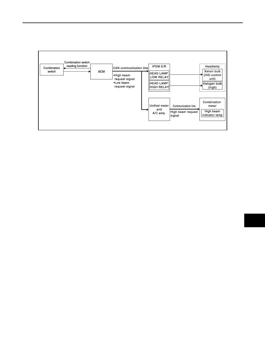
System Diagram
INFOID:0000000003534165
System Description
INFOID:0000000003534166
OUTLINE
Headlamp is controlled by combination switch reading function and headlamp control function of BCM, and
relay control function of IPDM E/R.
HEADLAMP (LO) OPERATION
• BCM detects the combination switch condition with the combination switch reading function.
• BCM transmits the low beam request signal to IPDM E/R with CAN communication according to the head-
lamp (LO) ON condition.
Headlamp (LO) ON condition
- Lighting switch 2ND
• IPDM E/R turns the integrated headlamp low relay ON, and turns the headlamp ON according to the low
beam request signal.
HEADLAMP (HI) OPERATION
• BCM transmits the high beam request signal to IPDM E/R and the combination meter (through the unified
meter and A/C amp.) with CAN communication according to the headlamp (HI) ON condition.
Headlamp (HI) ON condition
- Lighting switch HI with the lighting switch 2ND
- Lighting switch PASS
• Combination meter turns the high beam indicator lamp ON according to the high beam request signal.
• IPDM E/R turns the integrated headlamp high relay ON, and turns the headlamp ON according to the high
beam request signal.
JPLIA0910GB
Нет комментариевНе стесняйтесь поделиться с нами вашим ценным мнением.
Текст