Infiniti EX35. Manual — part 1328

SN
DIAGNOSIS AND REPAIR WORKFLOW
SN-3
< BASIC INSPECTION >
C
D
E
F
G
H
I
J
K
L
M
B
A
O
P
BASIC INSPECTION
DIAGNOSIS AND REPAIR WORKFLOW
Work Flow
INFOID:0000000003160532
DETAILED FLOW
1.
INTERVIEW FOR MALFUNCTION
Interview the conditions and environment when occurring any malfunction to the customer.
>> GO TO 2.
2.
SYMPTOM CHECK
• Check the symptom from the customer's information.
• Check that any malfunction occurs other than the malfunction interviewed from the customer.
>> GO TO 3.
3.
INSPECTION BEFORE DIAGNOSIS
Check the following conditions of the sensor.
• Check if the sonar sensor is not frozen.
• Check if snow, mud, or other foreign objects are not adhering to the sonar sensor.
• Check if there is no deformation, scratches, or other damage to the sonar sensor.
• Check if water has not accumulated in the sonar sensor.
Is the sensor condition normal?
YES
>> GO TO 4.
NO
>> Repair the sensor condition.
4.
SELF-DIAGNOSIS WITH CONSULT-III RESULT INSPECTION
Perform the self-diagnosis with CONSULT-III.
Is the inspection result normal?
YES
>> GO TO 5.
NO
>> GO TO 6.
5.
MALFUNCTIONING PART EXTRACTION BY SYMPTOM DIAGNOSIS
Repair the malfunctioning part by the symptom diagnosis.
>> GO TO 6.
6.
FINAL INSPECTION
Check that the sonar system activates normally.
Does the sonar system activate normally?
YES
>> INSPECTION END
NO
>> GO TO 1.
SN-4
< FUNCTION DIAGNOSIS >
SONAR SYSTEM
FUNCTION DIAGNOSIS
SONAR SYSTEM
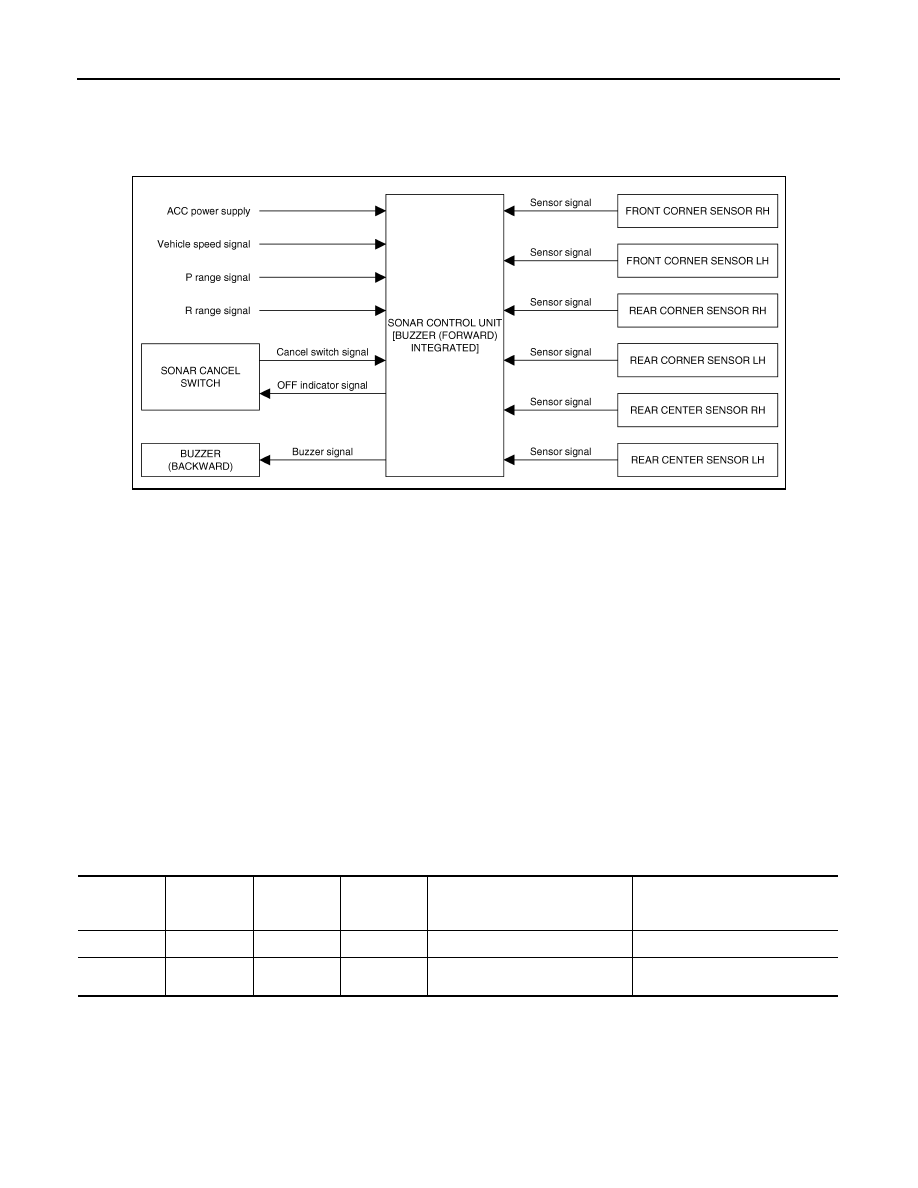
System Diagram
INFOID:0000000003160533
System Description
INFOID:0000000003160534
• The sonar sensor installed to the front bumper and the rear bumper detects obstacles around the bumper.
• The distance between the bumper and the obstacle is informed of the driver with different frequency and sort
of buzzers (low/high sound).
Activation condition
Front sensor
The front sensor activates and outputs the warning buzzer (low sound) in the following conditions.
• Cancel switch OFF
• P range signal OFF
• The vehicle speed signal is within the activation condition.
• Obstacle detection
Rear sensor
The rear sensor activates and outputs the warning buzzer (high sound) in the following conditions.
• Cancel switch OFF
• Reverse signal ON
• P range signal OFF
• Obstacle detection
x: applicable
NOTE:
*: If both the front and the rear sensors detect different objects simultaneously, the sensor which detects the closer object is prior to
another sensor. If the detection distance is equal between the front and the rear, the rear sensor is prior to the front sensor.
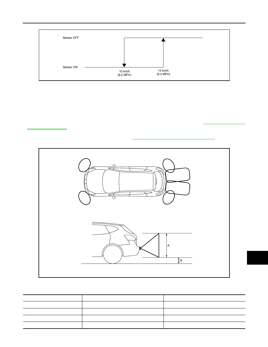
Vehicle speed signal activation condition range
• The sensor activation turns OFF when the vehicle drives at 15 km/h (9.3 MPH) or more to the forward direc-
tion.
JSNIA0727GB
Cancel
switch
Reverse
signal
P range
signal
Vehicle
speed signal
Front sensor
(Buzzer integrated in sonar control
unit)
Rear sensor
(Buzzer separated to other unit)
OFF
ON
OFF
—
X
*
X
*
OFF
OFF
OFF
Within the
condition
X
—
SN
SONAR SYSTEM
SN-5
< FUNCTION DIAGNOSIS >
C
D
E
F
G
H
I
J
K
L
M
B
A
O
P
• The sensor activation starts when the vehicle speed is 10 km/h (6.2 MPH) or less.
Obstacle detection distance
• The sonar control unit controls the obstacle detection distance. The detection distance differs between the
corner sensor and the center sensor.
• The sonar control unit outputs the warning buzzer frequency at 3 levels according to the corner sensor
detection condition.
• The sonar control unit outputs the warning buzzer frequency at 4 levels according to the center sensor
detection condition.
• The detection condition setting is adjustable to 4 levels with CONSULT-III. Refer to
.
• CONSULT-III enables the center sensor (rear) not to detect the range of 40 cm (15.7 in) or less to prevent
from the trailer hitch vehicles misdetection. Refer to
SN-8, "CONSULT-III Function (SONAR)"
.
Obstacle detection range image
Detection distance
JSNIA0309GB
JSNIA0753ZZ
A
Approx. 50 cm (19.6 in)
B.
Approx. 15 cm (5.9 in)
Warning item
Corner sensor
Center sensor
First stage warning
—
70 – 110 cm (27.5 – 43.3 in)
Second stage warning
60 – 70 cm (23.6 – 27.5 in)
60 – 70 cm (23.6 – 27.5 in)
Third stage warning
40 – 60 cm (15.7 – 23.6 in)
40 – 60 cm (15.7 – 23.6 in)
Fourth stage warning
Less than 40 cm (15.7 in)
Less than 40 cm (15.7 in)
SN-6
< FUNCTION DIAGNOSIS >
SONAR SYSTEM
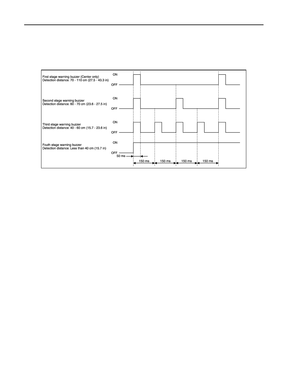
Warning buzzer frequency
• The warning buzzer output frequency changes 4 levels (for center) and 3 levels (for corner) according to the
detection distance.
• The nearest sensor from the detected obstacle applies the buzzer output frequency if plural sensors detect
any obstacle simultaneously.
• If both the front and the rear sensor detect different objects simultaneously, the sensor which detects the
closer object is prior to another sensor. If the detection distance is equal between the front and the rear,
warning buzzer of rear sounds. (The front and the rear buzzers do not output the sounds simultaneously.)
JSNIA0754GB
Нет комментариевНе стесняйтесь поделиться с нами вашим ценным мнением.
Текст