Infiniti EX35. Manual — part 671

EC-426
< COMPONENT DIAGNOSIS >
[VQ35HR]
P2127, P2128 APP SENSOR
YES
>> Go to
NO
>> INSPECTION END
Diagnosis Procedure
INFOID:0000000003133606
1.
CHECK GROUND CONNECTION
1.
Turn ignition switch OFF.
2.
Check ground connection M95. Refer to Ground Inspection in
Is the inspection result normal?
YES
>> GO TO 2.
NO
>> Repair or replace ground connection.
2.
CHECK APP SENSOR 2 POWER SUPPLY CIRCUIT-I
1.
Disconnect accelerator pedal position (APP) sensor harness connector.
2.
Turn ignition switch ON.
3.
Check the voltage between APP sensor harness connector and ground.
Is the inspection result normal?
YES
>> GO TO 7.
NO
>> GO TO 3.
3.
CHECK APP SENSOR 2 POWER SUPPLY CIRCUIT-II
1.
Turn ignition switch OFF.
2.
Disconnect ECM harness connector.
3.
Check the continuity between APP sensor harness connector and ECM harness connector.
Is the inspection result normal?
YES
>> GO TO 5.
NO
>> GO TO 4.
4.
DETECT MALFUNCTIONING PART
Check the following.
• Harness connectors M6, E106
• Harness for open or short between ECM and accelerator pedal position sensor
>> Repair open circuit.
5.
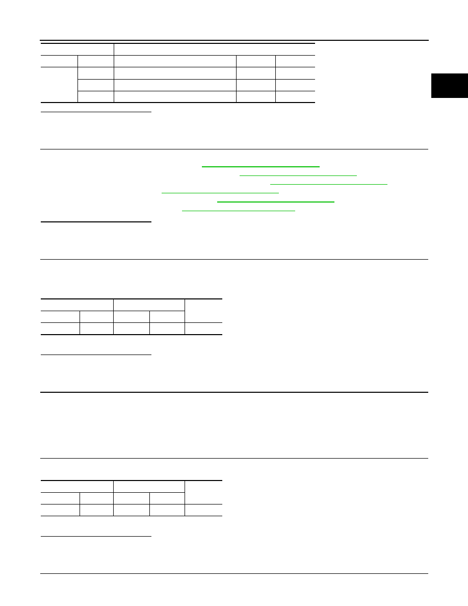
CHECK APP SENSOR 2 POWER SUPPLY CIRCUIT-III
Check harness for short to power and short to ground, between the following terminals.
APP sensor
Ground
Voltage
Connector
Terminal
E112
6
Ground
Approx. 5V
APP sensor
ECM
Continuity
Connector
Terminal
Connector
Terminal
E112
6
M107
103
Existed
ECM
Sensor
Connector
Terminal
Name
Connector
Terminal
F101
46
CKP sensor (POS)
F2
1
F102
64
CMP sensor (PHASE) (bank 2)
F18
1
EVT control position sensor (bank 2)
F19
1
Battery current sensor
E21
1
P2127, P2128 APP SENSOR
EC-427
< COMPONENT DIAGNOSIS >
[VQ35HR]
C
D
E
F
G
H
I
J
K
L
M
A
EC
N
P
O
Is the inspection result normal?
YES
>> GO TO 6.
NO
>> Repair short to ground or short to power in harness or connectors.
6.
CHECK COMPONENTS
Check the following.
• Crankshaft position sensor (POS) (Refer to
EC-255, "Component Inspection"
• Camshaft position sensor (PHASE) (bank 2) (Refer to
EC-260, "Component Inspection"
• Exhaust valve timing control position sensor (bank 2) (Refer to
EC-348, "Component Inspection"
.)
• Battery current sensor (Refer to
EC-379, "Component Inspection"
.)
• EVAP control system pressure sensor (Refer to
EC-296, "Component Inspection"
.)
• Refrigerant pressure sensor (Refer to
Is the inspection result normal?
YES
>> GO TO 13.
NO
>> Replace malfunctioning component.
7.
CHECK APP SENSOR 2 GROUND CIRCUIT FOR OPEN AND SHORT
1.
Turn ignition switch OFF.
2.
Disconnect ECM harness connector.
3.
Check the continuity between APP sensor harness connector and ECM harness connector.
4.
Also check harness for short to ground and short to power.
Is the inspection result normal?
YES
>> GO TO 9.
NO
>> GO TO 8.
8.
DETECT MALFUNCTIONING PART
Check the following.
• Harness connectors M6, E106
• Harness for open or short between ECM and accelerator pedal position sensor
>> Repair open circuit or short to ground or short to power in harness or connectors.
9.
CHECK APP SENSOR 2 INPUT SIGNAL CIRCUIT FOR OPEN AND SHORT
1.
Check the continuity between APP sensor harness connector and ECM harness connector.
2.
Also check harness for short to ground and short to power.
Is the inspection result normal?
YES
>> GO TO 11.
NO
>> GO TO 10.
10.
DETECT MALFUNCTIONING PART
Check the following.
M107
103
APP sensor
E112
6
107
EVAP control system pressure sensor
B252
3
111
Refrigerant pressure sensor
E77
3
ECM
Sensor
Connector
Terminal
Name
Connector
Terminal
APP sensor
ECM
Continuity
Connector
Terminal
Connector
Terminal
E112
2
M107
104
Existed
APP sensor
ECM
Continuity
Connector
Terminal
Connector
Terminal
E112
1
M107
98
Existed

EC-428
< COMPONENT DIAGNOSIS >
[VQ35HR]
P2127, P2128 APP SENSOR
• Harness connectors M6, E106
• Harness for open or short between ECM and accelerator pedal position sensor
>> Repair open circuit or short to ground or short to power in harness or connectors.
11.
CHECK APP SENSOR
EC-428, "Component Inspection"
Is the inspection result normal?
YES
>> GO TO 13.
NO
>> GO TO 12.
12.
REPLACE ACCELERATOR PEDAL ASSEMBLY
1.
Replace accelerator pedal assembly.
2.
Go to
EC-428, "Special Repair Requirement"
.
>> INSPECTION END
13.
CHECK INTERMITTENT INCIDENT
GI-38, "Intermittent Incident"
>> INSPECTION END
Component Inspection
INFOID:0000000003133607
1.
CHECK ACCELERATOR PEDAL POSITION SENSOR
1.
Turn ignition switch OFF.
2.
Reconnect all harness connectors disconnected.
3.
Turn ignition switch ON.
4.
Check the voltage ECM harness connector terminals as follows.
Is the inspection result normal?
YES
>> INSPECTION END
NO
>> GO TO 2.
2.
REPLACE ACCELERATOR PEDAL ASSEMBLY
1.
Replace accelerator pedal assembly.
2.
Go to
EC-428, "Special Repair Requirement"
.
>> INSPECTION END
Special Repair Requirement
INFOID:0000000003133608
1.
PERFORM ACCELERATOR PEDAL RELEASED POSITION LEARNING
Refer to
EC-17, "ACCELERATOR PEDAL RELEASED POSITION LEARNING : Special Repair Requirement"
.
>> GO TO 2.
ECM
Condition
Voltage (V)
Connector
+
–
Terminal
M107
97 (APP sensor 1)
100
Accelerator pedal
Fully released
0.5 - 1.0
Fully depressed
4.2 - 4.8
98 (APP sensor 2)
104
Fully released
0.25 - 0.50
Fully depressed
2.0 - 2.5

P2127, P2128 APP SENSOR
EC-429
< COMPONENT DIAGNOSIS >
[VQ35HR]
C
D
E
F
G
H
I
J
K
L
M
A
EC
N
P
O
2.
PERFORM THROTTLE VALVE CLOSED POSITION LEARNING
EC-17, "THROTTLE VALVE CLOSED POSITION LEARNING : Special Repair Requirement"
>> GO TO 3.
3.
PERFORM IDLE AIR VOLUME LEARNING
EC-18, "IDLE AIR VOLUME LEARNING : Special Repair Requirement"
>> END
Нет комментариевНе стесняйтесь поделиться с нами вашим ценным мнением.
Текст