Infiniti EX35. Manual — part 556
DLN-174
< DISASSEMBLY AND ASSEMBLY >
[REAR FINAL DRIVE: R200]
DIFFERENTIAL ASSEMBLY
4.
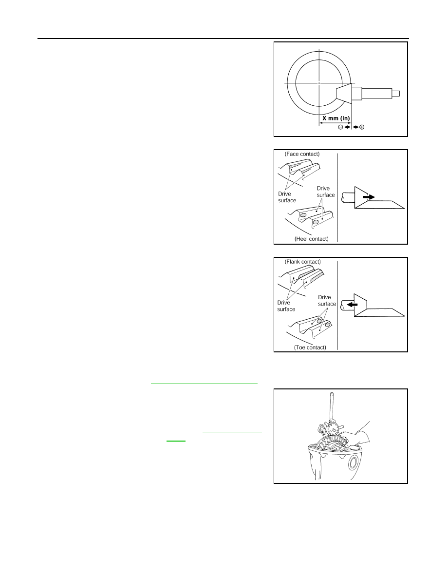
If tooth contact is improperly adjusted, follow the procedure
below to adjust the pinion height [dimension (X)].
• If the tooth contact is near the face (face contact), or near the
heel (heel contact), thicken pinion height adjusting washers to
move drive pinion closer to drive gear.
• If the tooth contact is near the flank (flank contact), or near the
toe (toe contact), thin pinion height adjusting washers to move
drive pinion farther from drive gear.
BACKLASH
Before inspection and adjustment, drain gear oil.
1.
Remove rear cover. Refer to
.
2.
Fit a dial indicator to the drive gear face to measure the back-
lash.
• If the backlash is outside of the specified value, change the
thickness of side bearing adjusting washer.
SDIA0517E
PDIA0440E
PDIA0441E
Standard
Backlash
: Refer to
.
When the backlash is large:
Make drive gear back side adjusting washer thicker,
and drive gear tooth side adjusting washer thinner by
the same amount.
When the backlash is small:
Make drive gear back side adjusting washer thinner,
and drive gear tooth side adjusting washer thicker by
the same amount.
SPD513
DIFFERENTIAL ASSEMBLY
DLN-175
< DISASSEMBLY AND ASSEMBLY >
[REAR FINAL DRIVE: R200]
C
E
F
G
H
I
J
K
L
M
A
B
DLN
N
O
P
CAUTION:
Never change the total amount of washers as it changes the bearing preload.
2WD : Inspection After Disassembly
INFOID:0000000003135835
DRIVE GEAR AND DRIVE PINION
• Clean up the disassembled parts.
• If the gear teeth never mesh or line-up correctly, determine the cause and adjust or replace as necessary.
• If the gears are worn, cracked, damaged, pitted or chipped (by friction) noticeably, replace with new drive
gear and drive pinion as a set.
BEARING
• Clean up the disassembled parts.
• If any chipped (by friction), pitted, worn, rusted or scratched marks, or unusual noise from the bearing is
observed, replace as a bearing assembly (as a new set).
SIDE GEAR AND PINION MATE GEAR
• Clean up the disassembled parts.
• If any cracks or damage on the surface of the tooth is found, replace.
• If any worn or chipped mark on the contact sides of the thrust washer is found, replace.
SIDE GEAR THRUST WASHER AND PINION MATE THRUST WASHER
• Clean up the disassembled parts.
• If it is chipped (by friction), damaged, or unusually worn, replace.
OIL SEAL
• Whenever disassembled, replace.
• If wear, deterioration of adherence (sealing force lips), or damage is detected on the lips, replace them.
DIFFERENTIAL CASE
• Clean up the disassembled parts.
• If any wear or crack on the contact sides of the differential case is found, replace.
COMPANION FLANGE
• Clean up the disassembled parts.
• If any chipped mark [about 0.1 mm, (0.004 in)] or other damage on the contact sides of the lips of the com-
panion flange is found, replace.
AWD
DLN-176
< DISASSEMBLY AND ASSEMBLY >
[REAR FINAL DRIVE: R200]
DIFFERENTIAL ASSEMBLY
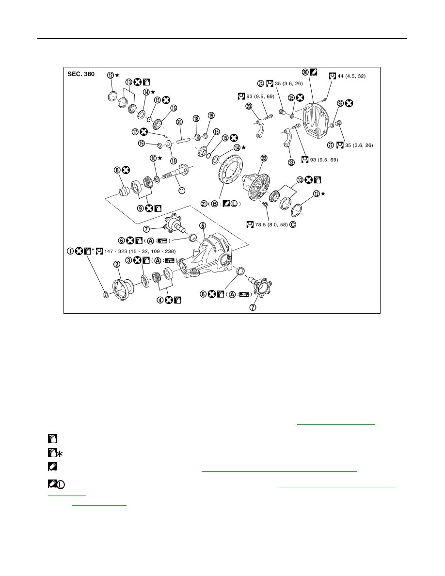
AWD : Exploded View
INFOID:0000000003135836
AWD : Disassembly
INFOID:0000000003135837
1.
Drain gear oil, if necessary.
2.
Remove side flange.
1.
Drive pinion lock nut
2.
Companion flange
3.
Front oil seal
4.
Pinion front bearing
5.
Gear carrier
6.
Side oil seal
7.
Side flange
8.
Collapsible spacer
9.
Pinion rear bearing
10. Pinion height adjusting washer
11.
Drive pinion
12. Side bearing adjusting washer
13. Side bearing
14. Side gear thrust washer
15. Circular clip
16. Side gear
17. Lock pin
18. Pinion mate gear
19. Pinion mate thrust washer
20. Pinion mate shaft
21. Drive gear
22. Differential case
23. Bearing cap
24. Filler plug
25. Gasket
26. Rear cover
27. Drain plug
A.
Oil seal lip
B.
Screw hole
C.
For the tightening torque, refer to
.
: Apply gear oil.
: Apply anti-corrosion oil.
: Apply Genuine Silicone RTV or equivalent. Refer to
GI-15, "Recommended Chemical Products and Sealants"
.
: Apply Genuine High Strength Thread Locking Sealant or equivalent. Refer to
GI-15, "Recommended Chemical Products
Refer to
for symbols not described above.
JSDIA0027GB
DIFFERENTIAL ASSEMBLY
DLN-177
< DISASSEMBLY AND ASSEMBLY >
[REAR FINAL DRIVE: R200]
C
E
F
G
H
I
J
K
L
M
A
B
DLN
N
O
P
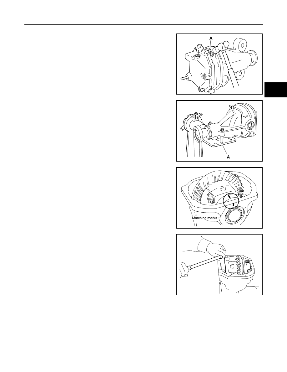
3.
Remove rear cover mounting bolts.
4.
Remove rear cover to insert the seal cutter (A) [SST:
KV10111100 (J-37228)] between gear carrier and rear cover.
CAUTION:
• Never damage the mating surface.
• Never insert flat-bladed screwdriver, this may damage the
mating surface.
5.
Using two 45 mm (1.77 in) spacers, mount carrier on the attach-
ment (A) [SST: KV38100800 (J-25604-01)].
6.
For proper reinstallation, paint matching marks on one side of
the bearing cap.
CAUTION:
• For matching marks, use paint. Never damage bearing
caps and gear carrier.
• Bearing caps are manufactured as integral molding. Use
the matching marks to them in their original positions.
7.
Remove bearing caps.
PDIA0756J
PDIA0757J
SDIA1795E
S-PD343
Нет комментариевНе стесняйтесь поделиться с нами вашим ценным мнением.
Текст