Infiniti EX35. Manual — part 448
DLK-6
BACK DOOR HINGE . . . . . . . . . . . ...
BACK DOOR HINGE : Exploded View . . . . ..
BACK DOOR HINGE : Removal and Installation ..
BACK DOOR STAY . . . . . . . . . . . . .
BACK DOOR STAY : Exploded View . . . . .
BACK DOOR STAY : Removal and Installation .
BACK DOOR WEATHER-STRIP . . . . . . . .
BACK DOOR WEATHER-STRIP : Exploded View ..
BACK DOOR WEATHER-STRIP : Removal and
Installation . . . . . . . . . . . . . . . .
HOOD LOCK . . . . . . . . . . . . ...
Exploded View . . . . . . . . . . . . . ...
Removal and Installation . . . . . . . . . ...
Inspection . . . . . . . . . . . . . . . ..
FRONT DOOR LOCK . . . . . . . . . ..
DOOR LOCK . . . . . . . . . . . . . . .
DOOR LOCK : Exploded View . . . . . . . ..
DOOR LOCK : Removal and Installation . . . ...
INSIDE HANDLE . . . . . . . . . . . . . ..
INSIDE HANDLE : Exploded View . . . . . .
INSIDE HANDLE : Removal and Installation . . .
OUTSIDE HANDLE . . . . . . . . . . . . ..
OUTSIDE HANDLE : Exploded View . . . . .
OUTSIDE HANDLE : Removal and Installation . .
REAR DOOR LOCK . . . . . . . . . .
DOOR LOCK . . . . . . . . . . . . . . .
DOOR LOCK : Exploded View . . . . . . . ..
DOOR LOCK : Removal and Installation . . . ...
INSIDE HANDLE . . . . . . . . . . . . . ..
INSIDE HANDLE : Exploded View . . . . . .
INSIDE HANDLE : Removal and Installation . . .
OUTSIDE HANDLE . . . . . . . . . . . . ..
OUTSIDE HANDLE : Exploded View . . . . .
OUTSIDE HANDLE : Removal and Installation . .
BACK DOOR LOCK . . . . . . . . . .
Exploded View . . . . . . . . . . . . . ...
Removal and Installation . . . . . . . . . ...
FUEL FILLER LID OPENER . . . . . . ...
Exploded View . . . . . . . . . . . . . ..
Removal and Installation . . . . . . . . . ...
DOOR SWITCH . . . . . . . . . . . .
Exploded View . . . . . . . . . . . . . ..
Removal and Installation . . . . . . . . . ...
INSIDE KEY ANTENNA . . . . . . . . ...
INSTRUMENT CENTER . . . . . . . . . . ..
INSTRUMENT CENTER : Exploded View . . .
INSTRUMENT CENTER : Removal and Installa-
tion . . . . . . . . . . . . . . . . . .
CONSOLE . . . . . . . . . . . . . . . ...
CONSOLE : Exploded View . . . . . . . . ..
CONSOLE : Removal and Installation . . . . ..
LUGGAGE ROOM . . . . . . . . . . . . ...
LUGGAGE ROOM : Exploded View . . . . . .
LUGGAGE ROOM : Removal and Installation . ..
OUTSIDE KEY ANTENNA . . . . . . . ...
DRIVER SIDE . . . . . . . . . . . . . . ..
DRIVER SIDE : Exploded View . . . . . . .
DRIVER SIDE : Removal and Installation . . . .
PASSENGER SIDE . . . . . . . . . . . . .
PASSENGER SIDE : Exploded View . . . . ...
PASSENGER SIDE : Removal and Installation .
BACK DOOR . . . . . . . . . . . . . . ...
BACK DOOR : Exploded View . . . . . . . ..
BACK DOOR : Removal and Installation . . . ..
INTELLIGENT KEY WARNING BUZZER . .
Exploded View . . . . . . . . . . . . . ..
Removal and Installation . . . . . . . . . ...
KEY SLOT . . . . . . . . . . . . . .
Exploded View . . . . . . . . . . . . . ..
Removal and Installation . . . . . . . . . ...
REMOTE KEYLESS ENTRY RECEIVER . .
Exploded View . . . . . . . . . . . . . ..
Removal and Installation . . . . . . . . . ...
INTELLIGENT KEY BATTERY . . . . . .
DIAGNOSIS AND REPAIR WORKFLOW
DLK-7
< BASIC INSPECTION >
[INTELLIGENT KEY SYSTEM]
C
D
E
F
G
H
I
J
L
M
A
B
DLK
N
O
P
BASIC INSPECTION
DIAGNOSIS AND REPAIR WORKFLOW
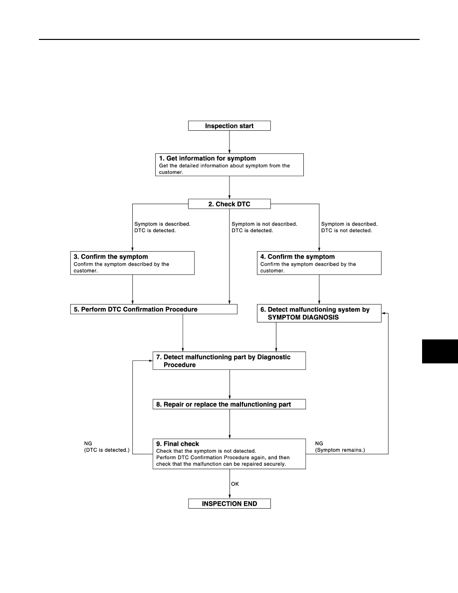
Work Flow
INFOID:0000000003739235
OVERALL SEQUENCE
DETAILED FLOW
JMKIA2270GB

DLK-8
< BASIC INSPECTION >
[INTELLIGENT KEY SYSTEM]
DIAGNOSIS AND REPAIR WORKFLOW
1.
GET INFORMATION FOR SYMPTOM
Get the detailed information from the customer about the symptom (the condition and the environment when
the incident/malfunction occurred).
>> GO TO 2.
2.
CHECK DTC
1.
Check DTC for BCM.
2.
Perform the following procedure if DTC is displayed.
-
Record DTC and freeze frame data (Print them out with CONSULT-III.)
-
Erase DTC.
-
Study the relationship between the cause detected by DTC and the symptom described by the customer.
3.
Check related service bulletins for information.
Is any symptom described and any DTC detected?
Symptom is described, DTC is displayed>>GO TO 3.
Symptom is described, DTC is not displayed>>GO TO 4.
Symptom is not described, DTC is displayed>>GO TO 5.
3.
CONFIRM THE SYMPTOM
Confirm the symptom described by the customer.
Connect CONSULT-III to the vehicle in “DATA MONITOR” mode and check real time diagnosis results.
Verify relation between the symptom and the condition when the symptom is detected.
>> GO TO 5.
4.
CONFIRM THE SYMPTOM
Confirm the symptom described by the customer.
Connect CONSULT-III to the vehicle in “DATA MONITOR” mode and check real time diagnosis results.
Verify relation between the symptom and the condition when the symptom is detected.
>> GO TO 6.
5.
PERFORM DTC CONFIRMATION PROCEDURE
Perform DTC Confirmation Procedure for the displayed DTC, and then check that DTC is detected again.
At this time, always connect CONSULT-III to the vehicle, and check diagnostic results in real time.
If two or more DTCs are detected, refer to
DLK-162, "DTC Inspection Priority Chart"
and determine trouble
diagnosis order.
NOTE:
Perform Component Function Check if DTC Confirmation Procedure is not included in Service Manual. This
simplified check procedure is an effective alternative though DTC cannot be detected during this check.
If the result of Component Function Check is NG, it is the same as the detection of DTC by DTC Confirmation
Procedure.
Is DTC detected?
YES
>> GO TO 7.
NO
>> Refer to
GI-38, "Intermittent Incident"
.
6.
DETECT MALFUNCTIONING SYSTEM BY SYMPTOM DIAGNOSIS
Detect malfunctioning system according to SYMPTOM DIAGNOSIS based on the confirmed symptom in step
4, and determine the trouble diagnosis order based on possible causes and symptom.
>> GO TO 7.
7.
DETECT MALFUNCTIONING PART BY DIAGNOSTIC PROCEDURE
Inspect according to Diagnostic Procedure of the system.
NOTE:
The Diagnostic Procedure described based on open circuit inspection. A short circuit inspection is also
required for the circuit check in the Diagnostic Procedure.

DIAGNOSIS AND REPAIR WORKFLOW
DLK-9
< BASIC INSPECTION >
[INTELLIGENT KEY SYSTEM]
C
D
E
F
G
H
I
J
L
M
A
B
DLK
N
O
P
Is malfunctioning part detected?
YES
>> GO TO 8.
NO
>> Check voltage of related BCM terminals using CONSULT-III.
8.
REPAIR OR REPLACE THE MALFUNCTIONING PART
1.
Repair or replace the malfunctioning part.
2.
Reconnect parts or connectors disconnected during Diagnostic Procedure again after repair and replace-
ment.
3.
Check DTC. If DTC is displayed, erase it.
>> GO TO 9.
9.
FINAL CHECK
When DTC was detected in step 2, perform DTC Confirmation Procedure or Component Function Check
again, and then check that the malfunction has been repaired securely.
When symptom was described from the customer, refer to confirmed symptom in step 3 or 4, and check that
the symptom is not detected.
Does the symptom reappear?
YES (DTC is detected)>>GO TO 7.
YES (Symptom remains)>>GO TO 6.
NO
>> INSPECTION END
Нет комментариевНе стесняйтесь поделиться с нами вашим ценным мнением.
Текст