Infiniti EX35. Manual — part 999
LAN
STRG BRANCH LINE CIRCUIT
LAN-55
< COMPONENT DIAGNOSIS >
[CAN]
C
D
E
F
G
H
I
J
K
L
B
A
O
P
N
STRG BRANCH LINE CIRCUIT
Diagnosis Procedure
INFOID:0000000003137655
1.
CHECK CONNECTOR
1.
Turn the ignition switch OFF.
2.
Disconnect the battery cable from the negative terminal.
3.
Check the terminals and connectors of the steering angle sensor for damage, bend and loose connection
(unit side and connector side).
Is the inspection result normal?
YES
>> GO TO 2.
NO
>> Repair the terminal and connector.
2.
CHECK HARNESS FOR OPEN CIRCUIT
1.
Disconnect the connector of steering angle sensor.
2.
Check the resistance between the steering angle sensor harness connector terminals.
Is the measurement value within the specification?
YES
>> GO TO 3.
NO
>> Repair the steering angle sensor branch line.
3.
CHECK POWER SUPPLY AND GROUND CIRCUIT
Check the power supply and the ground circuit of the steering angle sensor. Refer to
gram - BRAKE CONTROL SYSTEM -"
.
Is the inspection result normal?
YES (Present error)>>Replace the steering angle sensor. Refer to
BRC-113, "Removal and Installation"
.
YES (Past error)>>Error was detected in the steering angle sensor branch line.
NO
>> Repair the power supply and the ground circuit.
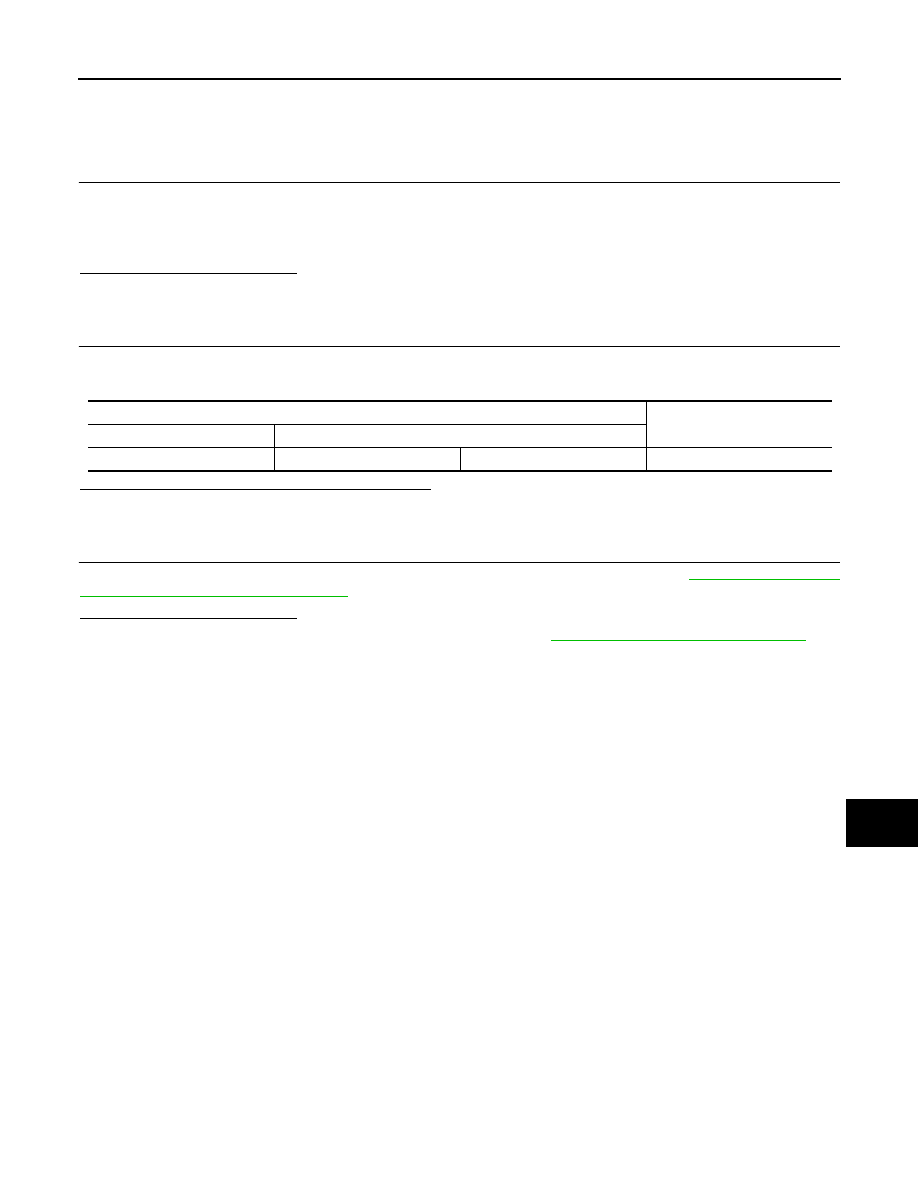
Steering angle sensor harness connector
Resistance (
Ω
)
Connector No.
Terminal No.
M37
1
2
Approx. 54 – 66
LAN-56
< COMPONENT DIAGNOSIS >
[CAN]
TCM BRANCH LINE CIRCUIT
TCM BRANCH LINE CIRCUIT
Diagnosis Procedure
INFOID:0000000003137651
1.
CHECK CONNECTOR
1.
Turn the ignition switch OFF.
2.
Disconnect the battery cable from the negative terminal.
3.
Check the following terminals and connectors for damage, bend and loose connection (unit side and con-
nector side).
-
A/T assembly
-
Harness connector F103
-
Harness connector M116
Is the inspection result normal?
YES
>> GO TO 2.
NO
>> Repair the terminal and connector.
2.
CHECK HARNESS FOR OPEN CIRCUIT
1.
Disconnect the connector of A/T assembly.
2.
Check the resistance between the A/T assembly harness connector terminals.
Is the measurement value within the specification?
YES
>> GO TO 3.
NO
>> Repair the TCM branch line.
3.
CHECK POWER SUPPLY AND GROUND CIRCUIT
Check the power supply and the ground circuit of the TCM. Refer to
.
Is the inspection result normal?
YES (Present error)>>Replace the control valve with TCM. Refer to
TM-162, "Removal and Installation"
YES (Past error)>>Error was detected in the TCM branch line.
NO
>> Repair the power supply and the ground circuit.
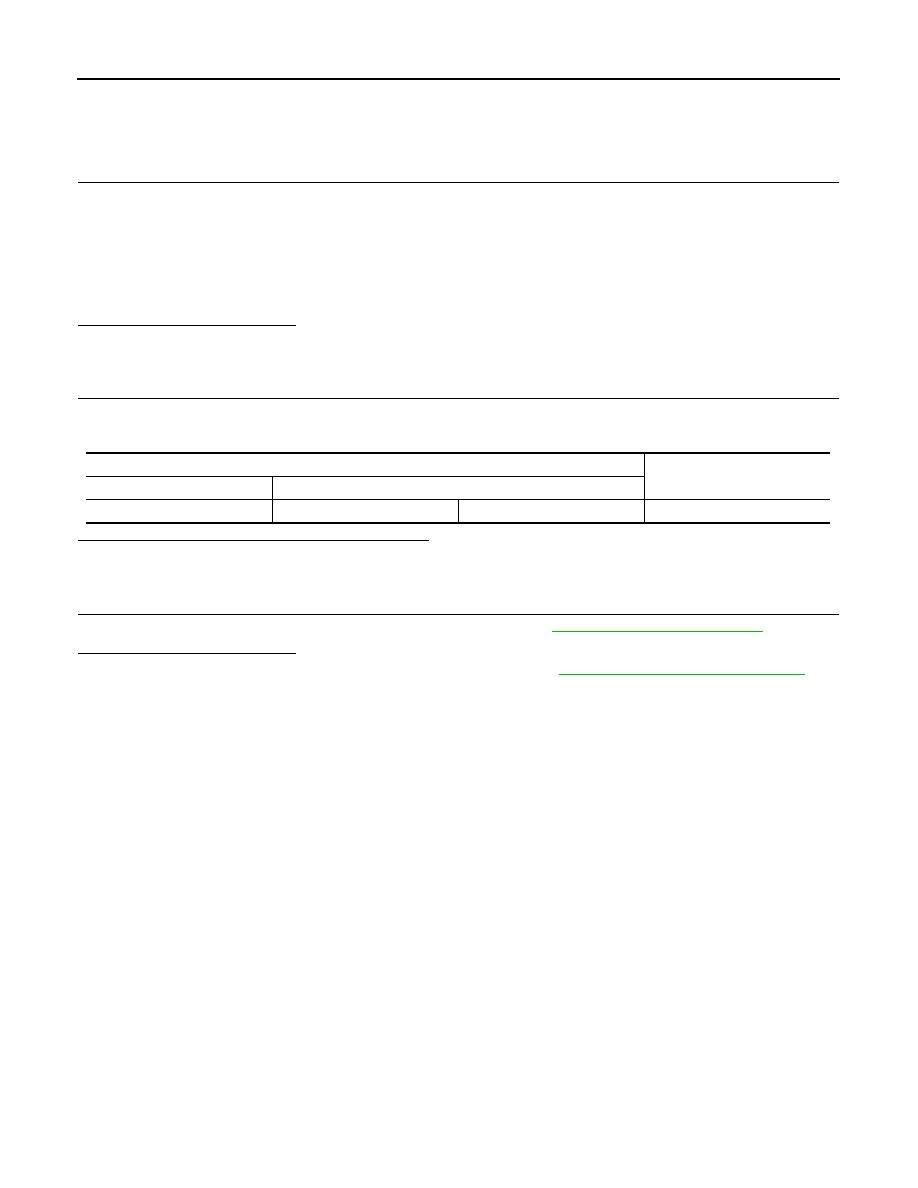
A/T assembly harness connector
Resistance (
Ω
)
Connector No.
Terminal No.
F51
3
8
Approx. 54 – 66
LAN
ADP BRANCH LINE CIRCUIT
LAN-57
< COMPONENT DIAGNOSIS >
[CAN]
C
D
E
F
G
H
I
J
K
L
B
A
O
P
N
ADP BRANCH LINE CIRCUIT
Diagnosis Procedure
INFOID:0000000003137656
1.
CHECK CONNECTOR
1.
Turn the ignition switch OFF.
2.
Disconnect the battery cable from the negative terminal.
3.
Check the following terminals and connectors for damage, bend and loose connection (unit side and con-
nector side).
-
Driver seat control unit
-
Harness connector B460
-
Harness connector B11
Is the inspection result normal?
YES
>> GO TO 2.
NO
>> Repair the terminal and connector.
2.
CHECK HARNESS FOR OPEN CIRCUIT
1.
Disconnect the connector of driver seat control unit.
2.
Check the resistance between the driver seat control unit harness connector terminals.
Is the measurement value within the specification?
YES
>> GO TO 3.
NO
>> Repair the driver seat control unit branch line.
3.
CHECK POWER SUPPLY AND GROUND CIRCUIT
Check the power supply and the ground circuit of the driver seat control unit. Refer to
CONTROL UNIT : Diagnosis Procedure"
Is the inspection result normal?
YES (Present error)>>Replace the driver seat control unit. Refer to
ADP-209, "Removal and Installation"
YES (Past error)>>Error was detected in the driver seat control unit branch line.
NO
>> Repair the power supply and the ground circuit.
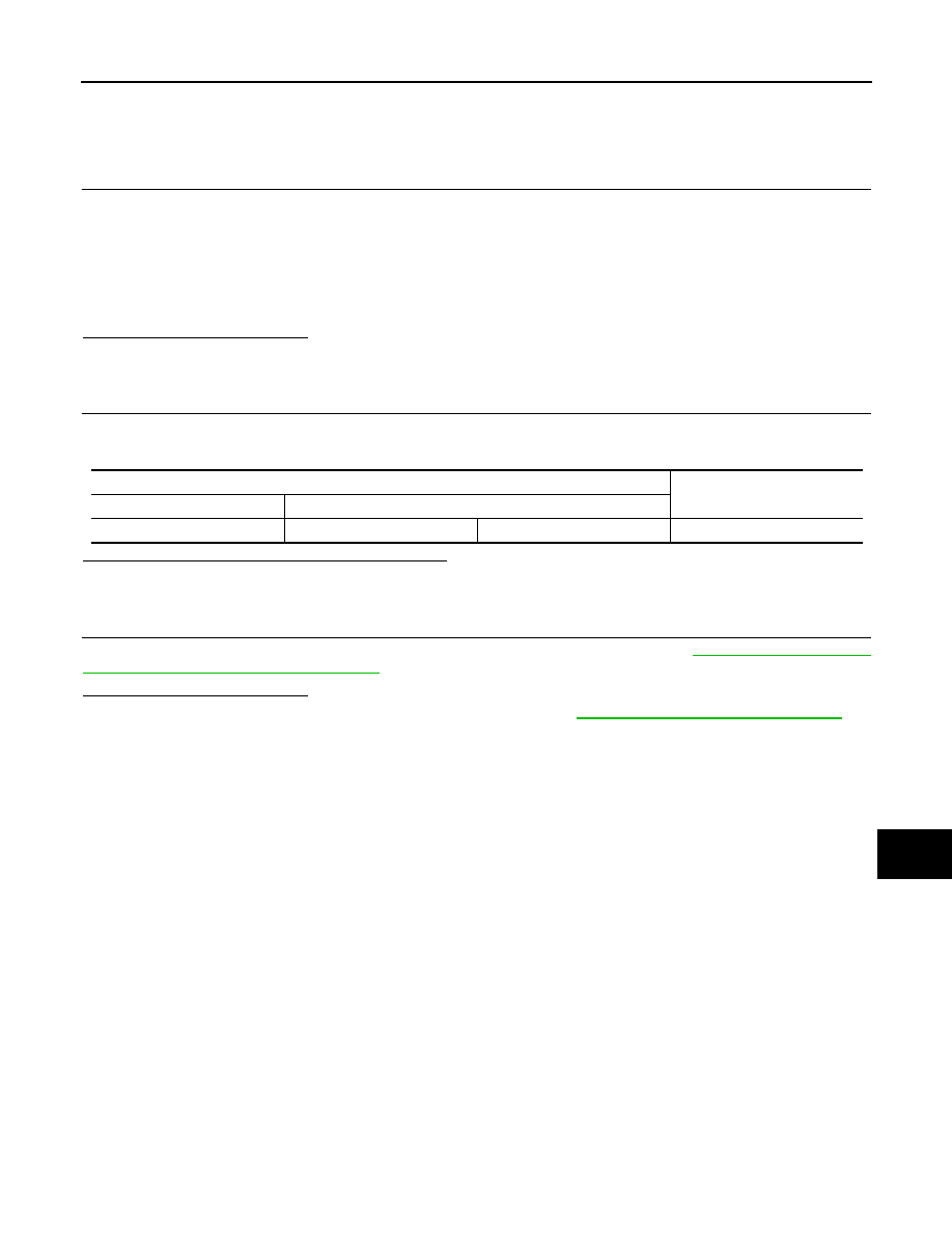
Driver seat control unit harness connector
Resistance (
Ω
)
Connector No.
Terminal No.
B451
3
19
Approx. 54 – 66
LAN-58
< COMPONENT DIAGNOSIS >
[CAN]
ABS BRANCH LINE CIRCUIT
ABS BRANCH LINE CIRCUIT
Diagnosis Procedure
INFOID:0000000003137658
1.
CHECK CONNECTOR
1.
Turn the ignition switch OFF.
2.
Disconnect the battery cable from the negative terminal.
3.
Check the terminals and connectors of the ABS actuator and electric unit (control unit) for damage, bend
and loose connection (unit side and connector side).
Is the inspection result normal?
YES
>> GO TO 2.
NO
>> Repair the terminal and connector.
2.
CHECK HARNESS FOR OPEN CIRCUIT
1.
Disconnect the connector of ABS actuator and electric unit (control unit).
2.
Check the resistance between the ABS actuator and electric unit (control unit) harness connector termi-
nals.
Is the measurement value within the specification?
YES
>> GO TO 3.
NO
>> Repair the ABS actuator and electric unit (control unit) branch line.
3.
CHECK POWER SUPPLY AND GROUND CIRCUIT
Check the power supply and the ground circuit of the ABS actuator and electric unit (control unit). Refer to
Is the inspection result normal?
YES (Present error)>>Replace the ABS actuator and electric unit (control unit). Refer to
.
YES (Past error)>>Error was detected in the ABS actuator and electric unit (control unit) branch line.
NO
>> Repair the power supply and the ground circuit.
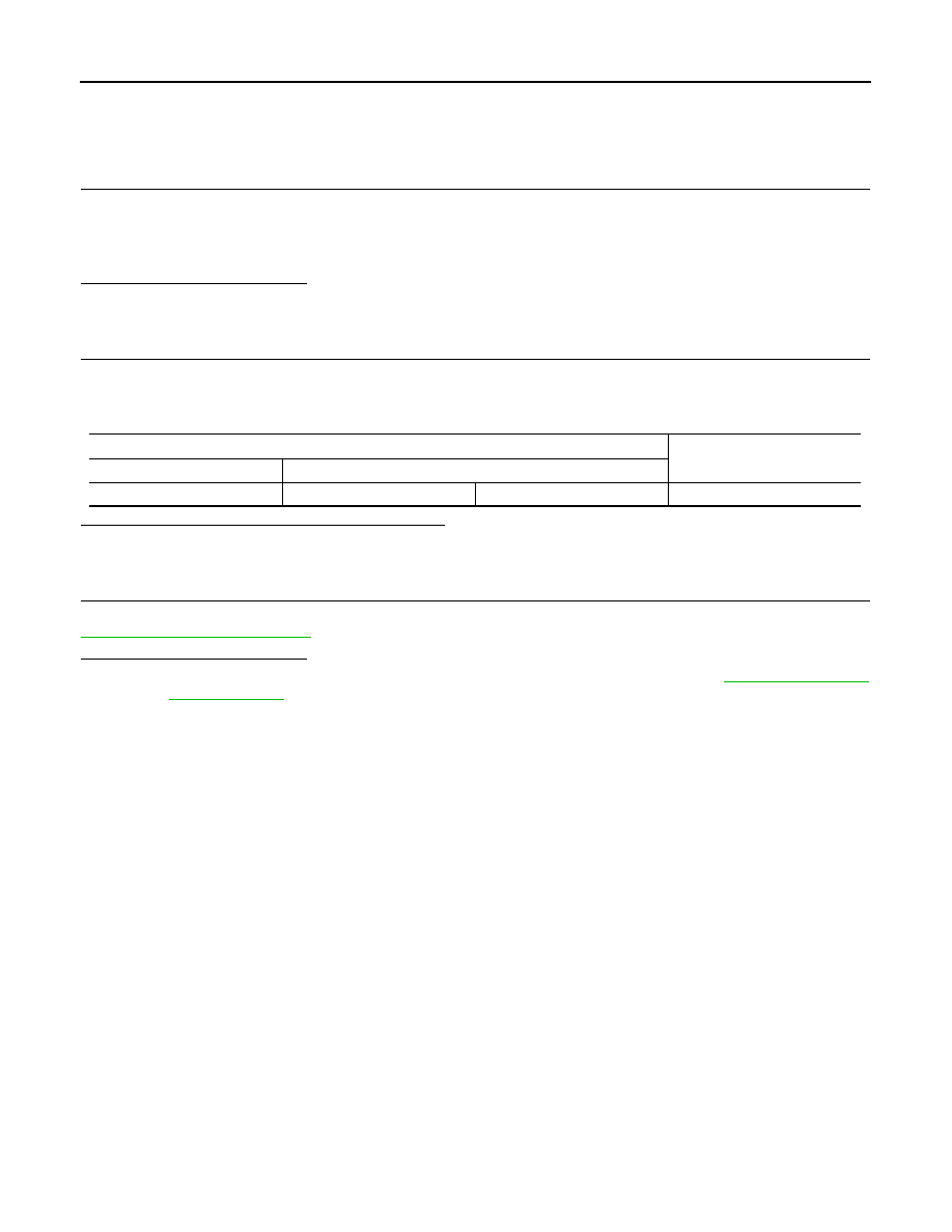
ABS actuator and electric unit (control unit) harness connector
Resistance (
Ω
)
Connector No.
Terminal No.
E41
35
14
Approx. 54 – 66
Нет комментариевНе стесняйтесь поделиться с нами вашим ценным мнением.
Текст