Infiniti EX35. Manual — part 322
BRC-3
C
D
E
G
H
I
J
K
L
M
A
B
BRC
N
O
P
VDC OFF SWITCH . . . . . . . . . . . .
Description . . . . . . . . . . . . . . . ..
Component Function Check . . . . . . . . .
Diagnosis Procedure . . . . . . . . . . . ...
Component Inspection . . . . . . . . . . .
ABS WARNING LAMP . . . . . . . . . ...
Description . . . . . . . . . . . . . . . ..
Component Function Check . . . . . . . . .
Diagnosis Procedure . . . . . . . . . . . ...
BRAKE WARNING LAMP . . . . . . . . .
Description . . . . . . . . . . . . . . . ..
Component Function Check . . . . . . . . .
Diagnosis Procedure . . . . . . . . . . . ...
VDC OFF INDICATOR LAMP . . . . . . .
Description . . . . . . . . . . . . . . . ..
Component Function Check . . . . . . . . .
Diagnosis Procedure . . . . . . . . . . . ...
SLIP INDICATOR LAMP . . . . . . . . .
Description . . . . . . . . . . . . . . . ..
Component Function Check . . . . . . . . .
Diagnosis Procedure . . . . . . . . . . . ...
ECU DIAGNOSIS . . . . . . . . . . .
ABS ACTUATOR AND ELECTRIC UNIT
(CONTROL UNIT) . . . . . . . . . . . ..
Reference Value . . . . . . . . . . . . . .
Wiring Diagram - BRAKE CONTROL SYSTEM - .
Fail-Safe . . . . . . . . . . . . . . . . ..
DTC No. Index . . . . . . . . . . . . . .
SYMPTOM DIAGNOSIS . . . . . . . ..
EXCESSIVE ABS FUNCTION OPERATION
FREQUENCY . . . . . . . . . . . . . .
Diagnosis Procedure . . . . . . . . . . . ...
UNEXPECTED PEDAL REACTION . . . . ..
Diagnosis Procedure . . . . . . . . . . . ...
THE BRAKING DISTANCE IS LONG . . . .
Diagnosis Procedure . . . . . . . . . . . ...
ABS FUNCTION DOES NOT OPERATE . . .
Diagnosis Procedure . . . . . . . . . . . .
PEDAL VIBRATION OR ABS OPERATION
SOUND OCCURS . . . . . . . . . . .
Diagnosis Procedure . . . . . . . . . . . .
VEHICLE JERKS DURING VDC/TCS/ABS
CONTROL . . . . . . . . . . . . . .
Diagnosis Procedure . . . . . . . . . . . .
NORMAL OPERATING CONDITION . . . .
Description . . . . . . . . . . . . . . . .
PRECAUTION . . . . . . . . . . .
PRECAUTIONS . . . . . . . . . . . ...
Precaution for Brake System . . . . . . . . .
Precaution for Brake Control . . . . . . . . .
Precautions for Harness Repair . . . . . . .
PREPARATION . . . . . . . . . . .
PREPARATION . . . . . . . . . . . ...
Special Service Tool . . . . . . . . . . . ..
Commercial Service Tool . . . . . . . . . ..
ON-VEHICLE REPAIR . . . . . . . ...
WHEEL SENSOR . . . . . . . . . . .
FRONT WHEEL SENSOR . . . . . . . . . ...
FRONT WHEEL SENSOR : Exploded View . . .
FRONT WHEEL SENSOR : Removal and Instal-
lation . . . . . . . . . . . . . . . . . ..
REAR WHEEL SENSOR . . . . . . . . . . .
REAR WHEEL SENSOR : Exploded View . . .
REAR WHEEL SENSOR : Removal and Installa-
tion . . . . . . . . . . . . . . . . . . .
SENSOR ROTOR . . . . . . . . . . .
FRONT SENSOR ROTOR . . . . . . . . . ...
FRONT SENSOR ROTOR : Exploded View . . .
FRONT SENSOR ROTOR : Removal and Instal-
lation . . . . . . . . . . . . . . . . . ..
REAR SENSOR ROTOR . . . . . . . . . . .
REAR SENSOR ROTOR : Exploded View . . .
REAR SENSOR ROTOR : Removal and Installa-
tion . . . . . . . . . . . . . . . . . . .
ABS ACTUATOR AND ELECTRIC UNIT
(CONTROL UNIT) . . . . . . . . . . ...
Exploded View . . . . . . . . . . . . . ...
Removal and Installation . . . . . . . . . ...
YAW RATE/SIDE G SENSOR . . . . . .
Exploded View . . . . . . . . . . . . . ...
Removal and Installation . . . . . . . . . ...
STEERING ANGLE SENSOR . . . . . . .
Exploded View . . . . . . . . . . . . . ...
BRC-4
< BASIC INSPECTION >
[VDC/TCS/ABS]
DIAGNOSIS AND REPAIR WORK FLOW
BASIC INSPECTION
DIAGNOSIS AND REPAIR WORK FLOW
Work Flow
INFOID:0000000003132853
PRECAUTIONS FOR DIAGNOSIS
If steering angle sensor, steering system parts, suspension system parts, ABS actuator and electric unit (con-
trol unit) or tires have been replaced, or if wheel alignment has been adjusted, be sure to adjust neutral posi-
tion of steering angle sensor before driving. Refer to
BRC-8, "ADJUSTMENT OF STEERING ANGLE
DIAGNOSIS AND REPAIR WORK FLOW
BRC-5
< BASIC INSPECTION >
[VDC/TCS/ABS]
C
D
E
G
H
I
J
K
L
M
A
B
BRC
N
O
P
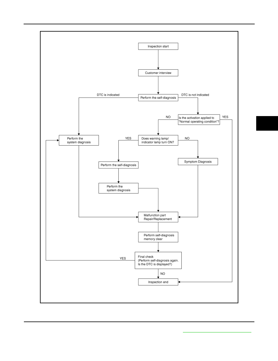
OVERALL SEQUENCE
DETAILED FLOW
1.
COLLECT THE INFORMATION FROM THE CUSTOMER
Get the detailed information from the customer about the symptom (the condition and the environment when
the incident/malfunction occurred) using the diagnosis work sheet. Refer to
BRC-7, "Diagnostic Work Sheet"
.
>> GO TO 2.
JSFIA0239GB

BRC-6
< BASIC INSPECTION >
[VDC/TCS/ABS]
DIAGNOSIS AND REPAIR WORK FLOW
2.
PERFORM THE SELF-DIAGNOSIS
Check the DTC display with the self-diagnosis function.
Is there any DTC displayed?
YES
>> GO TO 3.
NO
>> GO TO 4.
3.
PERFORM THE SYSTEM DIAGNOSIS
Perform the diagnosis applicable to the displayed DTC. Refer to
>> GO TO 7.
4.
CHECK THE SYMPTOM THAT IS NOT CONSIDERED A SYSTEM MALFUNCTION
Check that the symptom is a normal operation that is not considered a system malfunction. Refer to
Is the symptom a normal operation?
YES
>> INSPECTION END
NO
>> GO TO 5.
5.
CHECK THE WARNING LAMP AND INDICATOR LAMP FOR ILLUMINATION
Check that the warning lamp and indicator lamp illuminate.
• ABS warning lamp: Refer to
.
• Brake warning lamp: Refer to
• VDC OFF indicator lamp: Refer to
.
• SLIP indicator lamp: Refer to
.
Is ON/OFF timing normal?
YES
>> GO TO 6.
NO
>> GO TO 2.
6.
PERFORM THE DIAGNOSIS BY SYMPTOM
Perform the diagnosis applicable to the symptom.
>> GO TO 7.
7.
REPAIR OR REPLACE THE MALFUNCTIONING PARTS
Repair or replace the specified malfunctioning parts.
>> GO TO 8.
8.
MEMORY CLEAR
Perform self-diagnosis memory clear.
>> GO TO 9.
9.
FINAL CHECK
Perform the self-diagnosis again, and check that the malfunction is repaired completely.
Is no other DTC present and the repair completed?
YES
>> INSPECTION END
NO
>> GO TO 3.
Нет комментариевНе стесняйтесь поделиться с нами вашим ценным мнением.
Текст