Infiniti EX35. Manual — part 314
BR-18
< ON-VEHICLE REPAIR >
BRAKE PEDAL
ON-VEHICLE REPAIR
BRAKE PEDAL
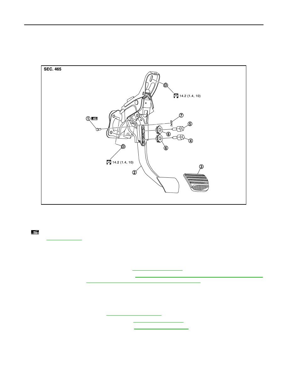
Exploded View
INFOID:0000000003139979
Removal and Installation
INFOID:0000000003139980
REMOVAL
1.
Remove instrument lower panel LH. Refer to
2.
Remove steering column assembly. Refer to
ST-17, "WITHOUT ELECTRIC MOTOR : Exploded View"
(without electric motor),
ST-20, "WITH ELECTRIC MOTOR : Exploded View"
3.
Disconnect the stop lamp switch and ASCD brake switch harness connectors.
4.
Turn the stop lamp switch and ASCD brake switch counterclockwise to remove the stop lamp switch and
ASCD brake switch.
5.
Remove snap pin and clevis pin from clevis of brake booster.
6.
Remove cowl top cover. Refer to
.
7.
Remove instrument panel assembly. Refer to
8.
Slide the steering member rearward. Refer to
.
9.
Remove brake pedal assembly.
INSTALLATION
Note the following, and install in the reverse order of removal.
1.
Clevis pin
2.
Brake pedal assembly
3.
Brake pedal pad
4.
ASCD brake switch
5.
Stop lamp switch
6.
Clip
7.
Snap pin
: Apply multi-purpose grease.
Refer to
for symbols not described on the above.
JPFIA0322GB
BRAKE PEDAL
BR-19
< ON-VEHICLE REPAIR >
C
D
E
G
H
I
J
K
L
M
A
B
BR
N
O
P
• Apply the multi-purpose grease to the clevis pin and the mating faces. (Not necessary if grease has been
already applied)
NOTE:
The clevis pin may be inserted in either direction.
Inspection and Adjustment
INFOID:0000000003139981
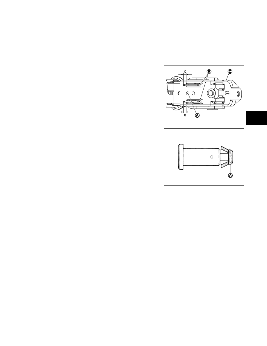
INSPECTION AFTER REMOVAL
• Check the following items and replace the brake pedal assembly if
necessary.
- Check the brake pedal upper rivet (made by aluminum) (A) for
deformation.
- Check the brake pedal for bend, damage, and cracks on the
welded parts.
- Check the lapping length (X) of sub-bracket (B) and slide plate (C).
• Check clevis pin and plastic stopper (A) for damage and deforma-
tion. If any is found, replace clevis pin.
ADJUSTMENT AFTER INSTALLATION
Perform the brake pedal adjustment after installing the brake pedal assembly. Refer to
.
Standard
X
: 5.0 mm (0.197 in) or more
JPFIA0323ZZ
PFIA0756J

BR-20
< ON-VEHICLE REPAIR >
BRAKE PIPING
BRAKE PIPING
FRONT
FRONT : Exploded View
INFOID:0000000003139982
1.
Brake tube
2.
Connector
3.
Master cylinder
4.
Brake booster
5.
ABS actuator and electric unit (con-
trol unit)
6.
Lock plate
7.
Union bolt
8.
Brake hose
9.
Copper washer
10. Brake hose bracket
11.
Brake tube
A.
To rear brake tube
B.
To front brake hose
C.
To front brake tube
Refer to
for symbols in the figure.
JPFIA0324GB

BRAKE PIPING
BR-21
< ON-VEHICLE REPAIR >
C
D
E
G
H
I
J
K
L
M
A
B
BR
N
O
P
FRONT : Hydraulic Piping
INFOID:0000000003139983
FRONT : Removal and Installation
INFOID:0000000003139984
REMOVAL
CAUTION:
Never spill or splash brake fluid on painted surfaces. Brake fluid may seriously damage paint. Wipe it
off immediately and wash with water if it gets on a painted surface.
1.
Remove tires with power tool.
2.
Drain brake fluid. Refer to
3.
Loosen the flare nut with a flare nut wrench and separate the brake tube from the hose.
CAUTION:
• Never scratch the flare nut and the brake tube.
• Never bend sharply, twist or strongly pull out the brake hoses and tubes.
• Cover open end of brake tubes and hoses when disconnecting to prevent entrance of dirt.
4.
Remove the union bolt and copper washers, and remove the brake hose from the brake caliper assembly.
5.
Remove the brake hose mounting nut.
6.
Remove the lock plate and remove the brake hose.
INSTALLATION
CAUTION:
Never spill or splash brake fluid on painted surfaces. Brake fluid may seriously damage paint. Wipe it
off immediately and wash with water if it gets on a painted surface.
1.
Assemble the union bolt and the copper washer to the brake hose.
CAUTION:
Never reuse the copper washer.
1.
ABS actuator and electric unit (con-
trol unit)
2.
Front disc brake
3.
Master cylinder
4.
Brake booster
5.
Connector
6.
Rear disc brake
A.
Brake hose
B.
Brake tube
: Flare nut
: Union bolt
JPFIA0335ZZ
Нет комментариевНе стесняйтесь поделиться с нами вашим ценным мнением.
Текст