Infiniti EX35. Manual — part 271
AV
SONAR CONTROL UNIT (WITH AROUND VIEW MONITOR)
AV-865
< ECU DIAGNOSIS >
[BOSE AUDIO WITH NAVIGATION]
C
D
E
F
G
H
I
J
K
L
M
B
A
O
P
SONAR CONTROL UNIT (WITH AROUND VIEW MONITOR)
Reference Value
INFOID:0000000003160754
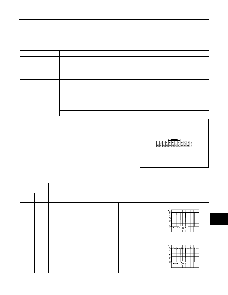
VALUES ON THE DIAGNOSIS TOOL
TERMINAL LAYOUT
PHYSICAL VALUES
Monitor Item
Display
Description
SONAR OPE
On
Around view monitor operating (sonar operating).
Off
Around view monitor non-operating (sonar non-operating).
BUZZER OUTPUT
On
Buzzer is output condition.
Off
Buzzer is not output condition.
CR SEN [FL]
CR SEN [FR]
CR SEN [RL]
CR SEN [RR]
ERROR
When a sensor is abnormal.
LV.0
When a sensor is not detection.
LV.2
The distance between the corner sensor and an obstacle is 50 cm (19.6 in) or more and
less then 60 cm (23.6 in).
LV.3
The distance between the corner sensor and an obstacle is 30 cm (11.8 in) or more and
less then 50 cm (19.6 in).
LV.4
The distance between corner sensor and an obstacle less than 30 cm (11.8 in).
JSNIA0303ZZ
Terminal No.
(Wire color)
Description
Condition
Value
(Approx.)
+
–
Signal name
Input/
Output
3
(R)
12
(B)
Corner sensor signal front
LH
Input
Ignition
switch
ON
“CAMERA” switch is ON or
shift position is “R”.
4
(W)
12
(B)
Corner sensor signal front
RH
Input
Ignition
switch
ON
“CAMERA” switch is ON or
shift position is “R”.
JSNIA0837GB
JSNIA0837GB
AV-866
< ECU DIAGNOSIS >
[BOSE AUDIO WITH NAVIGATION]
SONAR CONTROL UNIT (WITH AROUND VIEW MONITOR)
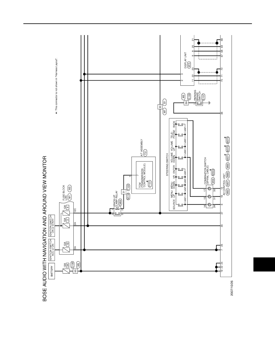
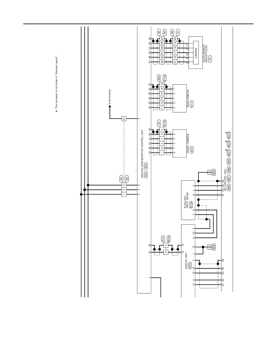
Wiring Diagram - BOSE AUDIO WITH NAVIGATION AND AROUND VIEW MONITOR
-
INFOID:0000000003737139
Click here to view the eWD.
NOTE:
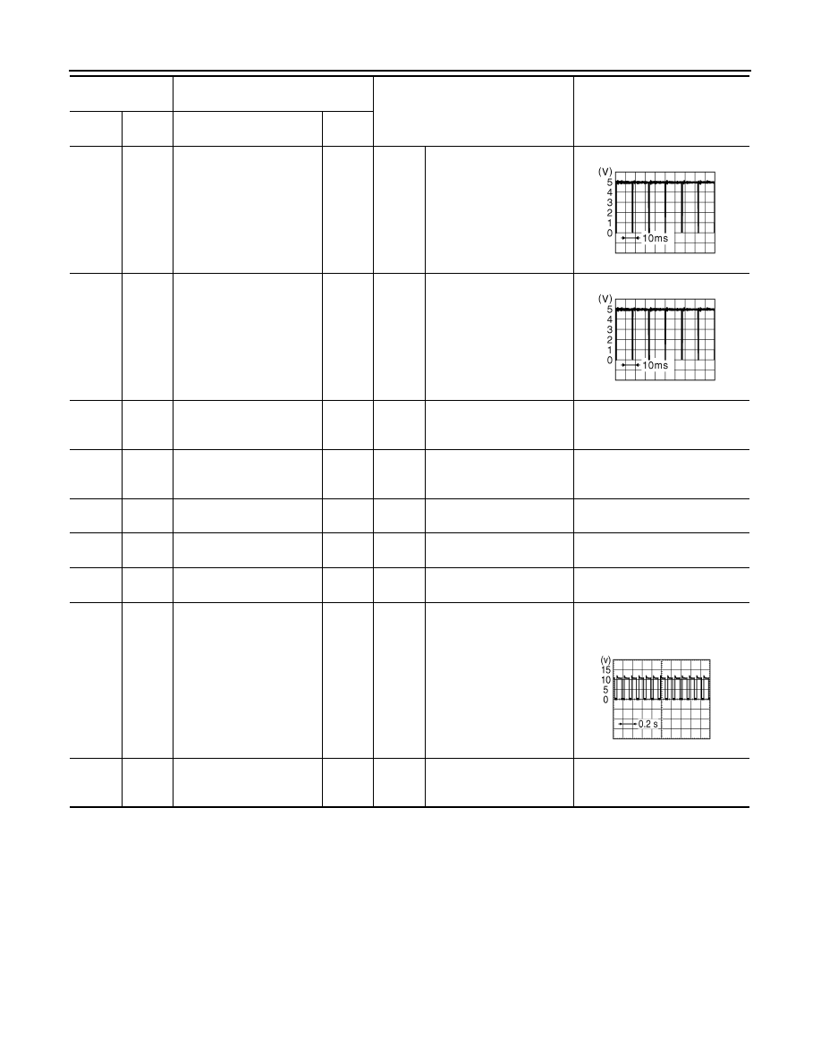
5
(W)
12
(B)
Corner sensor signal rear
LH
Input
Ignition
switch
ON
“CAMERA” switch is ON or
shift position is “R”.
6
(W/R)
12
(B)
Corner sensor signal rear
RH
Input
Ignition
switch
ON
“CAMERA” switch is ON or
shift position is “R”.
12
(B)
Ground
Sensor ground
—
Ignition
switch
ON
—
0 V
13
(V)
Ground
ACC power supply
Input
Ignition
switch
ACC
—
12.0 V
18
(O)
—
K-line (CONSULT-III)
—
—
—
—
19
(G)
—
AV communication (H)
Input/
Output
—
—
—
20
(R)
—
AV communication (L)
Input/
Output
—
—
—
23
(GR)
Ground
Buzzer drive signal
Output
Ignition
switch
ON
When buzzer operation
NOTE:
Waveform period changes due to
the distance to an obstacle.
24
(B)
Ground
Ground
—
Ignition
switch
ON
—
0 V
Terminal No.
(Wire color)
Description
Condition
Value
(Approx.)
+
–
Signal name
Input/
Output
JSNIA0837GB
JSNIA0837GB
SKIB8943E
AV
SONAR CONTROL UNIT (WITH AROUND VIEW MONITOR)
AV-867
< ECU DIAGNOSIS >
[BOSE AUDIO WITH NAVIGATION]
C
D
E
F
G
H
I
J
K
L
M
B
A
O
P
The name MULTIFUNCTION SWITCH indicates the integration of PRESET SWITCH and MULTIFUNCTION
SWITCH virtually.
JCNWM0793GB
AV-868
< ECU DIAGNOSIS >
[BOSE AUDIO WITH NAVIGATION]
SONAR CONTROL UNIT (WITH AROUND VIEW MONITOR)
JCNWM0794GB
Нет комментариевНе стесняйтесь поделиться с нами вашим ценным мнением.
Текст