Infiniti EX35. Manual — part 190

AV
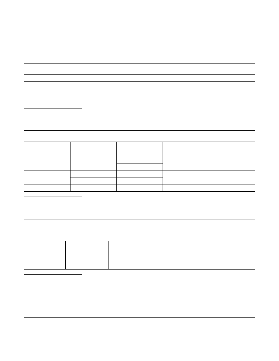
B2705 SENSOR HARNESS OPEN [CR-RL]
AV-541
< COMPONENT DIAGNOSIS >
[BOSE AUDIO WITH NAVIGATION]
C
D
E
F
G
H
I
J
K
L
M
B
A
O
P
B2705 SENSOR HARNESS OPEN [CR-RL]
Description
INFOID:0000000003513811
DTC Logic
INFOID:0000000003510922
DTC DETECTION LOGIC
Diagnosis Procedure
INFOID:0000000003510923
1.
CHECK HARNESS CORNER SENSOR REAR LH SIGNAL CIRCUIT
1.
Turn ignition switch OFF.
2.
Disconnect sonar control unit connector and corner sensor connector.
3.
Check continuity between sonar control unit harness connector and corner sensor (RL) harness connec-
tor.
4.
Check continuity between sonar control unit harness connector and ground.
Is the inspection result normal?
YES
>> GO TO 2.
NO
>> Repair harness or connector.
2.
CHECK HARNESS CORNER SENSOR REAR LH GROUND CIRCUIT
Check continuity between sonar control unit harness connector and corner sensor (RL) harness connector.
Is the inspection result normal?
YES
>> INSPECTION END
NO
>> Repair harness or connector.
Component
Description
CORNER SENSOR
The obstacle distance is detected. The signal is transmitted to the sonar control unit.
DTC No.
CONSULT-III indication
DTC detection condition
Troubleshooting
B2705
SENSOR HARNESS
OPEN [CR-RL] [B2705]
Corner sensor rear left harness circuit is open.
Check corner sensor rear LH circuit.
Sonar control unit
Corner sensor (RL)
Continuity
Connector
Terminal
Connector
Terminal
M47
5
B259
1
Existed
Sonar control unit
Ground
Continuity
Connector
Terminal
M47
5
Not existed
Sonar control unit
Corner sensor (RL)
Continuity
Connector
Terminal
Connector
Terminal
M47
12
B259
2
Existed

AV-542
< COMPONENT DIAGNOSIS >
[BOSE AUDIO WITH NAVIGATION]
B2706 CORNER SENSOR [RR]
B2706 CORNER SENSOR [RR]
Description
INFOID:0000000003513812
DTC Logic
INFOID:0000000003510925
DTC DETECTION LOGIC
Component
Description
CORNER SENSOR
The obstacle distance is detected. The signal is transmitted to the sonar control unit.
DTC No.
CONSULT-III indication
DTC detection condition
Troubleshooting
B2706
CORNER SENSOR [RR]
[B2706]
Corner sensor rear right is malfunctioning.
Replace corner sensor rear RH.

AV
B2707 SENSOR HARNESS OPEN [CR-RR]
AV-543
< COMPONENT DIAGNOSIS >
[BOSE AUDIO WITH NAVIGATION]
C
D
E
F
G
H
I
J
K
L
M
B
A
O
P
B2707 SENSOR HARNESS OPEN [CR-RR]
Description
INFOID:0000000003513813
DTC Logic
INFOID:0000000003510927
DTC DETECTION LOGIC
Diagnosis Procedure
INFOID:0000000003510928
1.
CHECK HARNESS CORNER SENSOR REAR RH SIGNAL CIRCUIT
1.
Turn ignition switch OFF.
2.
Disconnect sonar control unit connector and corner sensor connector.
3.
Check continuity between sonar control unit harness connector and corner sensor (RR) harness connec-
tor.
4.
Check continuity between sonar control unit harness connector and ground.
Is the inspection result normal?
YES
>> GO TO 2.
NO
>> Repair harness or connector.
2.
CHECK HARNESS CORNER SENSOR REAR RH GROUND CIRCUIT
Check continuity between sonar control unit harness connector and corner sensor (RR) harness connector.
Is the inspection result normal?
YES
>> INSPECTION END
NO
>> Repair harness or connector.
Component
Description
CORNER SENSOR
The obstacle distance is detected. The signal is transmitted to the sonar control unit.
DTC No.
CONSULT-III indication
DTC detection condition
Troubleshooting
B2707
SENSOR HARNESS
OPEN [CR-RR] [B2707]
Corner sensor rear right harness circuit is open.
Check corner sensor rear RH circuit.
Sonar control unit
Corner sensor (RR)
Continuity
Connector
Terminal
Connector
Terminal
M47
6
B256
1
Existed
Sonar control unit
Ground
Continuity
Connector
Terminal
M47
6
Not existed
Sonar control unit
Corner sensor (RR)
Continuity
Connector
Terminal
Connector
Terminal
M47
12
B256
2
Existed
AV-544
< COMPONENT DIAGNOSIS >
[BOSE AUDIO WITH NAVIGATION]
POWER SUPPLY AND GROUND CIRCUIT
POWER SUPPLY AND GROUND CIRCUIT
AV CONTROL UNIT
AV CONTROL UNIT : Diagnosis Procedure
INFOID:0000000003160695
1.
CHECK FUSE
Check for blown fuses.
Is inspection result normal?
YES
>> GO TO 2.
NO
>> Be sure to eliminate cause of malfunction before installing new fuse.
2.
CHECK POWER SUPPLY CIRCUIT
Check voltage between AV control unit harness connectors and ground.
Is inspection result normal?
YES
>> GO TO 3.
NO
>> Check harness between AV control unit and fuse.
3.
CHECK GROUND CIRCUIT
1.
Turn ignition switch OFF.
2.
Disconnect AV control unit connectors.
3.
Check continuity between AV control unit harness connectors and ground.
Is inspection result normal?
YES
>> INSPECTION END
NO
>> Repair harness or connector.
DISPLAY UNIT
DISPLAY UNIT : Diagnosis Procedure
INFOID:0000000003160696
1.
CHECK FUSE
Check for blown fuses.
Power source
Fuse No.
Battery
34
Ignition switch ACC or ON
19
Ignition switch ON or START
3
Signal name
Connector No.
Terminal No.
Ignition switch position
Value (Approx.)
Battery power supply
M80
19
OFF
Battery voltage
M87
22
24
ACC power supply
M80
7
ACC
Battery voltage
M87
25
Ignition signal
M87
35
ON
Battery voltage
Signal name
Connector No.
Terminal No.
Ignition switch position
Continuity
Ground
M80
20
OFF
Existed
M87
21
23
Нет комментариевНе стесняйтесь поделиться с нами вашим ценным мнением.
Текст