Infiniti EX35. Manual — part 28

ADP-106
< COMPONENT DIAGNOSIS >
MIRROR SENSOR
Is the indication normal?
YES
>> INSPECTION END
NO
>> Perform diagnosis procedure. Refer to
ADP-106, "PASSENGER SIDE : Diagnosis Procedure"
.
PASSENGER SIDE : Diagnosis Procedure
INFOID:0000000003134748
1.
CHECK DOOR MIRROR SENSOR (PASSENGER SIDE) POWER SUPPLY
1.
Turn ignition switch OFF.
2.
Disconnect door mirror (passenger side) connector.
3.
Turn ignition switch ON.
4.
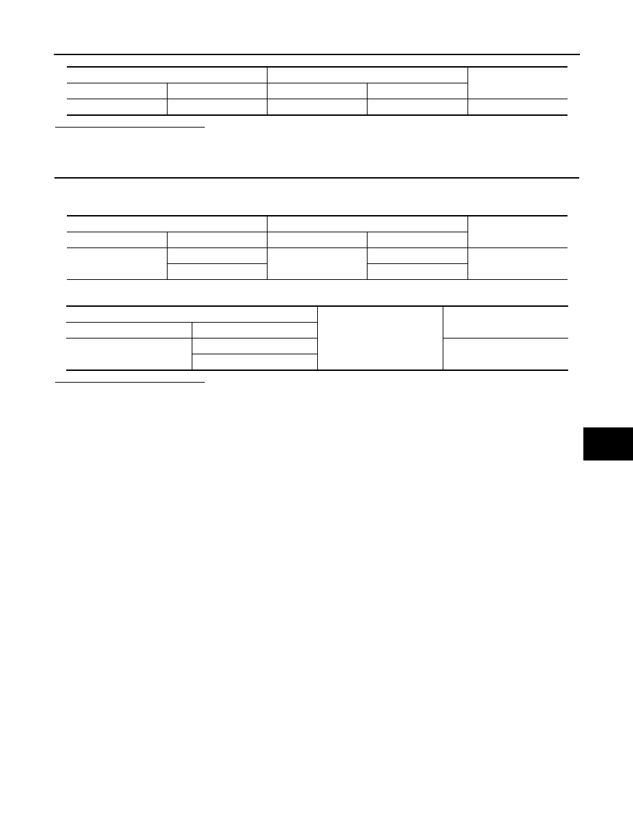
Check voltage between door mirror (passenger side) harness connector and ground.
Is the inspection result normal?
YES
>> GO TO 3.
NO
>> GO TO 2.
2.
CHECK DOOR MIRROR (PASSENGER SIDE) SENSOR POWER SUPPLY CIRCUIT
1.
Turn ignition switch OFF.
2.
Disconnect automatic drive positioner control unit connector.
3.
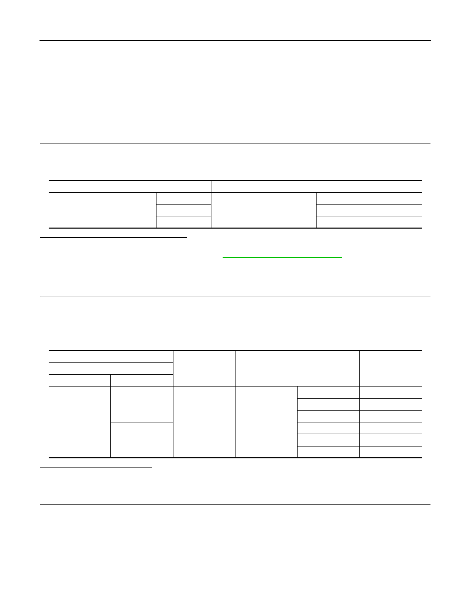
Check continuity between automatic drive positioner control unit harness connector and door mirror (pas-
senger side) harness connector.
4.
Check continuity between automatic drive positioner control unit harness connector and ground.
Is the inspection result normal?
YES
>> Replace automatic driver positioner control unit. Refer to
ADP-210, "Removal and Installation"
NO
>> Repair or replace harness or connector.
3.
CHECK DOOR MIRROR (PASSENGER SIDE) SENSOR GROUND
1.
Turn ignition switch OFF.
2.
Disconnect automatic drive positioner control unit connector.
3.
Check continuity between automatic drive positioner control unit harness connector and door mirror (pas-
senger side) connector.
Monitor item
Condition
Value
MIR/SEN RH U-D
Door mirror (passenger side)
Change between
3.4 [V] (close to peak)
0.6 [V] (close to valley)
MIR/SEN RH R-L
Change between
3.4 [V] (close to left edge)
0.6 [V] (close to right edge)
(+)
(–)
Voltage (V)
(Approx.)
Door mirror (passenger side)
Connector
Terminal
D33
23
Ground
5
Automatic drive positioner control unit
Door mirror (passenger side)
Continuity
Connector
Terminal
Connector
Terminal
M52
33
D33
23
Existed
Automatic drive positioner control unit
Ground
Continuity
Connector
Terminal
M52
33
Not existed
MIRROR SENSOR
ADP-107
< COMPONENT DIAGNOSIS >
C
D
E
F
G
H
I
K
L
M
A
B
ADP
N
O
P
Is the inspection result normal?
YES
>> GO TO 4.
NO
>> Repair or replace harness or connector.
4.
CHECK DOOR MIRROR (PASSENGER SIDE) SENSOR HARNESS CONTINUITY
1.
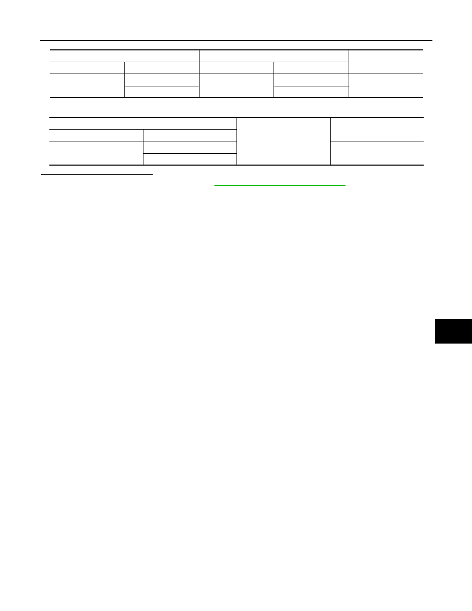
Check continuity between automatic drive positioner control unit harness connector and door mirror (pas-
senger side) harness connector.
2.
Check continuity between automatic drive positioner control unit harness connector and ground.
Is the inspection result normal?
YES
>> Replace door mirror sensor. (Built in passenger side door mirror).
NO
>> Repair or replace harness or connector.
Automatic drive positioner control unit
Door mirror (passenger side)
Continuity
Connector
Terminal
Connector
Terminal
M52
41
D33
24
Existed
Automatic drive positioner control unit
Door mirror (passenger side)
Continuity
Connector
Terminal
Connector
Terminal
M51
5
D33
21
Existed
21
22
Automatic drive positioner control unit
Ground
Continuity
Connector
Terminal
M51
5
Not existed
21
ADP-108
< COMPONENT DIAGNOSIS >
SLIDING MOTOR
SLIDING MOTOR
Description
INFOID:0000000003134749
• The seat sliding motor is installed to the seat cushion frame.
• The seat sliding motor is installed with the driver seat control unit.
• The seat is slid frontward/rearward by changing the rotation direction of sliding motor.
Component Function Check
INFOID:0000000003134750
1.
CHECK FUNCTION
1.
Turn ignition switch ON.
2.
Select “SEAT SLIDE” in “Active test” mode with CONSULT-III.
3.
Check the sliding motor operation.
Is the operation of relevant parts normal?
YES
>> INSPECTION END
NO
>> Perform diagnosis procedure. Refer to
ADP-108, "Diagnosis Procedure"
Diagnosis Procedure
INFOID:0000000003134751
1.
CHECK SLIDING MOTOR POWER SUPPLY
1.
Turn ignition switch OFF.
2.
Disconnect sliding motor connector.
3.
Turn the ignition switch ON.
4.
Perform “Active test” (“SEAT SLIDE”) with CONSULT-lll
5.
Check voltage between sliding motor harness connector and ground.
Is the inspection result normal?
YES
>> Replace sliding motor. (Built in seat slide cushion frame.)
NO
>> GO TO 2.
2.
CHECK SLIDING MOTOR CIRCUIT
1.
Turn ignition switch OFF.
2.
Disconnect driver seat control unit connector.
3.
Check continuity between driver seat control unit harness connector and sliding motor harness connector.
Test item
Description
SEAT SLIDE
OFF
Seat sliding
Stop
FR
Forward
RR
Backward
(+)
(-)
Condition
Voltage (V)
(Approx.)
Sliding motor
Connector
Terminal
B461
35
Ground
SEAT SLIDE
OFF
0
FR (forward)
Battery voltage
RR (backward)
0
42
OFF
0
FR (forward)
0
RR (backward)
Battery voltage
SLIDING MOTOR
ADP-109
< COMPONENT DIAGNOSIS >
C
D
E
F
G
H
I
K
L
M
A
B
ADP
N
O
P
4.
Check continuity between driver seat control unit harness connector and ground.
Is the inspection result normal?
YES
>> Replace driver control unit. Refer to
ADP-209, "Removal and Installation"
NO
>> Repair or replace harness or connector.
Driver seat control unit
Sliding motor
Continuity
Connector
Terminal
Connector
Terminal
B452
35
B461
35
Existed
42
42
Driver seat control unit
Ground
Continuity
Connector
Terminal
B452
35
Not existed
42
Нет комментариевНе стесняйтесь поделиться с нами вашим ценным мнением.
Текст