Infiniti EX35. Manual — part 1228
BCM (BODY CONTROL MODULE)
RF-37
< ECU DIAGNOSIS >
C
D
E
F
G
H
I
J
L
M
A
B
RF
N
O
P
108
(R)
Ground
Combination switch
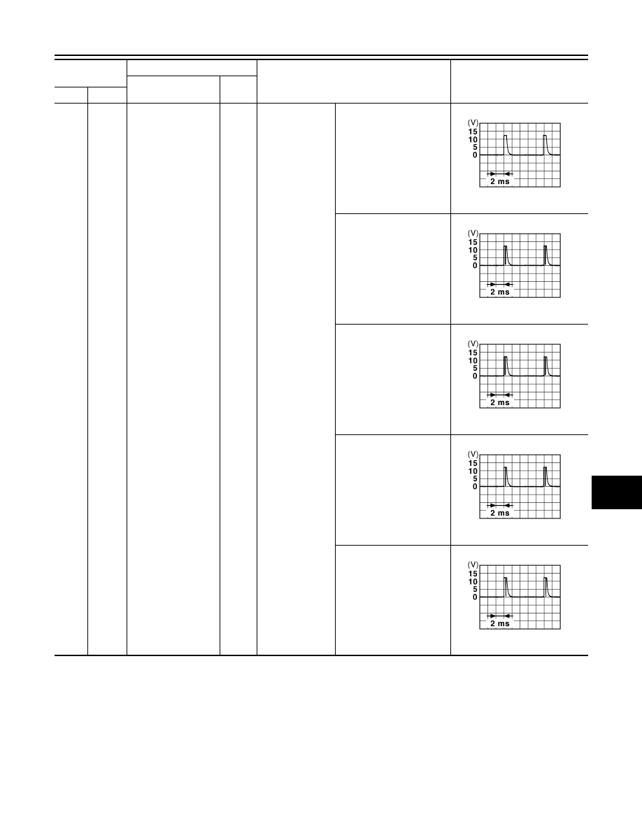
INPUT 4
Input
Combination
switch
All switch OFF
(Wiper intermittent dial 4)
1.4 V
Lighting switch AUTO
(Wiper intermittent dial 4)
1.3 V
Lighting switch 1ST
(Wiper intermittent dial 4)
1.3 V
Rear wiper switch INT
(Wiper intermittent dial 4)
1.3 V
Any of the conditions below
with all switch OFF
• Wiper intermittent dial 1
• Wiper intermittent dial 5
• Wiper intermittent dial 6
1.3 V
Terminal No.
(Wire color)
Description
Condition
Value
(Approx.)
Signal name
Input/
Output
+
–
JPMIA0041GB
JPMIA0038GB
JPMIA0036GB
JPMIA0040GB
JPMIA0039GB
RF-38
< ECU DIAGNOSIS >
BCM (BODY CONTROL MODULE)
109
(Y)
Ground
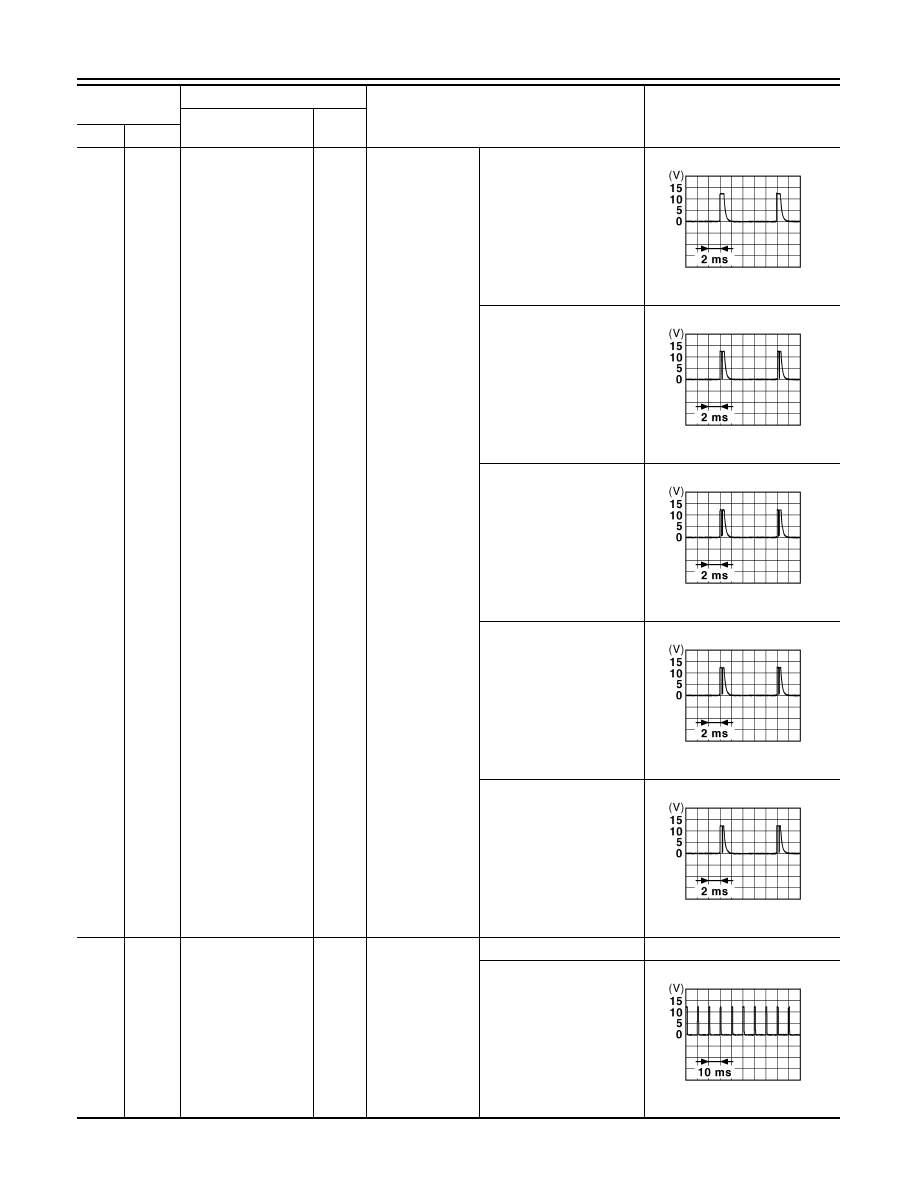
Combination switch
INPUT 2
Input
Combination
switch
(Wiper intermit-
tent dial 4)
All switch OFF
1.4 V
Lighting switch PASS
1.3 V
Lighting switch 2ND
1.3 V
Front wiper switch INT
1.3 V
Front wiper switch HI
1.3 V
110
(G)
Ground
Hazard switch
Input
Hazard switch
ON
0 V
OFF
1.1 V
Terminal No.
(Wire color)
Description
Condition
Value
(Approx.)
Signal name
Input/
Output
+
–
JPMIA0041GB
JPMIA0037GB
JPMIA0036GB
JPMIA0038GB
JPMIA0040GB
JPMIA0012GB
BCM (BODY CONTROL MODULE)
RF-39
< ECU DIAGNOSIS >
C
D
E
F
G
H
I
J
L
M
A
B
RF
N
O
P
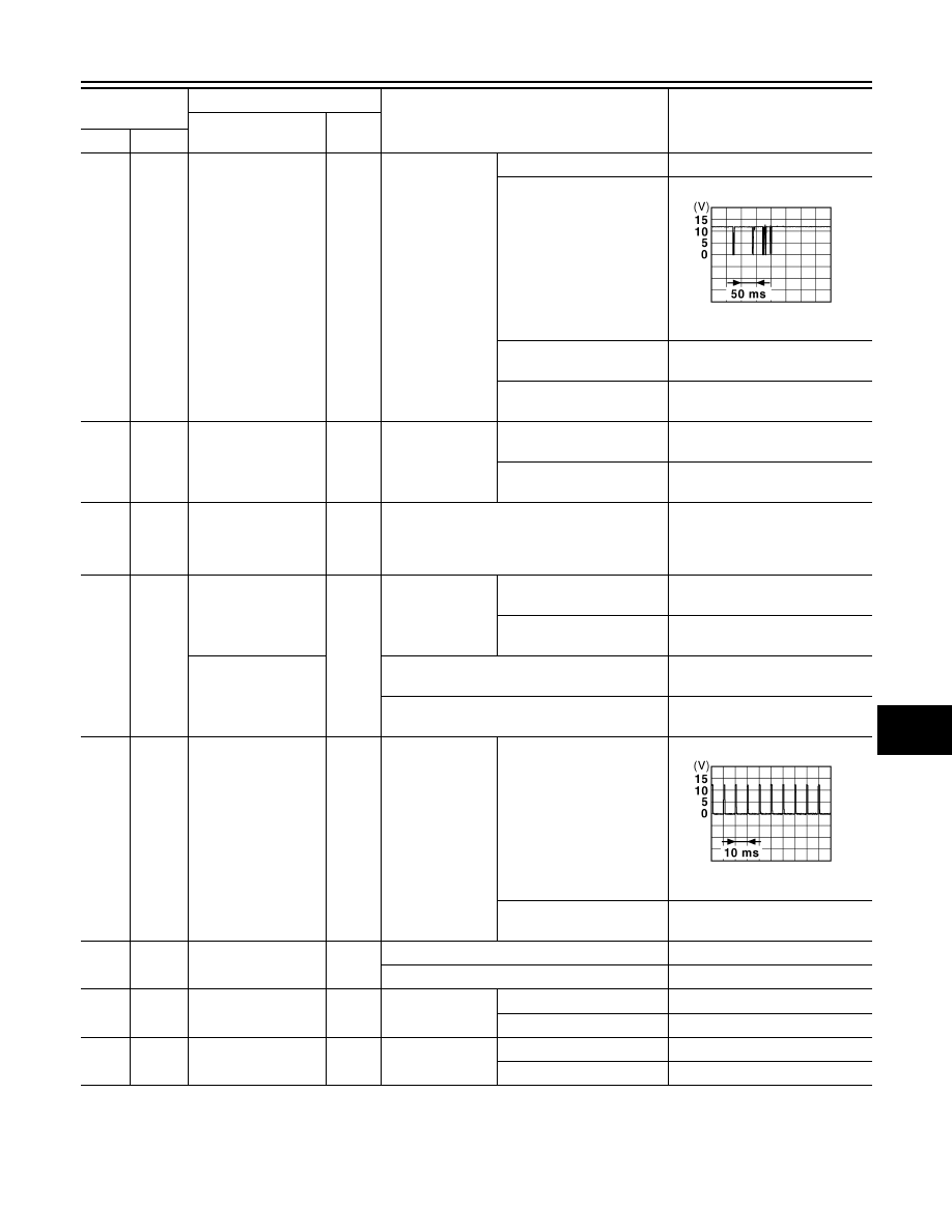
111
(Y)
Ground
Steering lock unit
communication
Input/
Output
Steering lock
LOCK status
Battery voltage
LOCK or UNLOCK
For 15 seconds after UN-
LOCK
Battery voltage
15 seconds or later after
UNLOCK
0 V
113*
(P)
Ground
Optical sensor signal
Input
Ignition switch
ON
When bright outside of the
vehicle
Close to 5 V
When dark outside of the
vehicle
Close to 0 V
116
(SB)
Ground
Fuse check [Stop
lamp switch, ICC
brake hold relay
(With ICC)]
Input
—
Battery voltage
118
(P)
Ground
Stop lamp switch
(Without ICC)
Input
Stop lamp switch
OFF (Brake pedal is not
depressed)
0 V
ON (Brake pedal is de-
pressed)
Battery voltage
Stop lamp switch and
ICC brake hold relay
(With ICC)
Stop lamp switch OFF (Brake pedal is not de-
pressed) and ICC brake hold relay OFF
0 V
Stop lamp switch ON (Brake pedal is de-
pressed) or ICC brake hold relay ON
Battery voltage
119
(SB)
Ground
Front door lock as-
sembly driver side
(unlock sensor)
Input
Driver door
LOCK status
(Unlock sensor switch
OFF)
1.1 V
UNLOCK status
(Unlock switch sensor ON)
0 V
121
(BR)
Ground
Key slot switch
Input
When the key is inserted into key slot
Battery voltage
When the key is not inserted into key slot
0 V
122
(V)
Ground
ACC feedback signal
Input
Ignition switch
OFF
0 V
ACC or ON
Battery voltage
123
(W)
Ground
IGN feedback signal
Input
Ignition switch
OFF or ACC
0 V
ON
Battery voltage
Terminal No.
(Wire color)
Description
Condition
Value
(Approx.)
Signal name
Input/
Output
+
–
JMKIA0066GB
JPMIA0012GB
RF-40
< ECU DIAGNOSIS >
BCM (BODY CONTROL MODULE)
124
(LG)
Ground
Passenger door
switch
Input
Passenger door
switch
OFF (Door close)
11.8 V
ON (Door open)
0 V
132
(V)
Ground
Power window switch
communication
Input/
Output
Ignition switch ON
10.2 V
Ignition switch OFF or ACC
Battery voltage
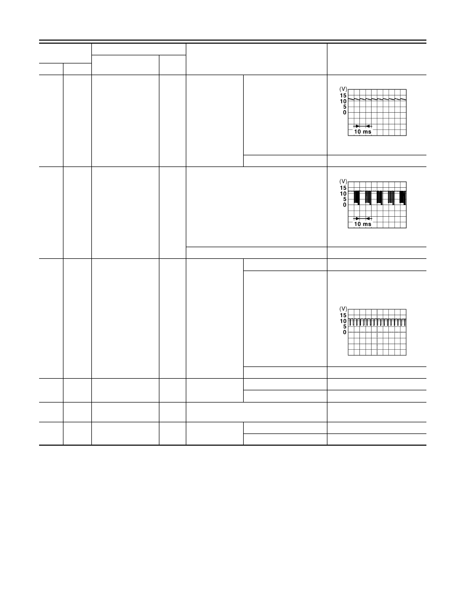
133
(W)
Ground
Push-button ignition
switch illumination
Output
Push-button igni-
tion switch illumi-
nation
ON (Tail lamps OFF)
9.5 V
ON (Tail lamps ON)
NOTE:
The pulse width of this wave is
varied by the illumination bright-
ening/dimming level.
OFF
0 V
134
(GR)
Ground
LOCK indicator lamp
Output
LOCK indicator
lamp
OFF
Battery voltage
ON
0 V
137
(O)
Ground
Receiver and sensor
ground
Input
Ignition switch ON
0 V
138
(Y)
Ground
Sensor power supply
Output
Ignition switch
OFF
0 V
ACC or ON
5.0 V
Terminal No.
(Wire color)
Description
Condition
Value
(Approx.)
Signal name
Input/
Output
+
–
JPMIA0011GB
JPMIA0013GB
JPMIA0159GB
Нет комментариевНе стесняйтесь поделиться с нами вашим ценным мнением.
Текст