Infiniti EX35. Manual — part 285
AV
CAMERA CONTROL UNIT
AV-921
< ON-VEHICLE REPAIR >
[BOSE AUDIO WITH NAVIGATION]
C
D
E
F
G
H
I
J
K
L
M
B
A
O
P
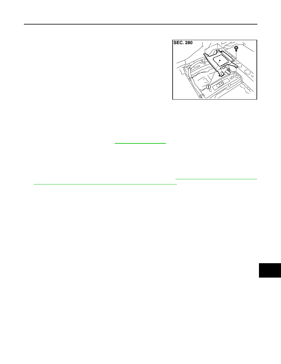
CAMERA CONTROL UNIT
Exploded View
INFOID:0000000003160801
Removal and Installation
INFOID:0000000003160802
REMOVAL
1.
Remove front seat (LH side). Refer to
.
2.
Remove floor carpet. Keep a service area.
3.
Remove camera control unit.
INSTALLATION
1.
Installation is the reverse order of removal.
2.
Perform predicted course line center position adjustment. Refer to
AV-437, "PREDICTED COURSE LINE
CENTER POSITION ADJUSTMENT : Special Repair Requirement"
JPNIA0883ZZ
1.
Camera control unit
AV-922
< ON-VEHICLE REPAIR >
[BOSE AUDIO WITH NAVIGATION]
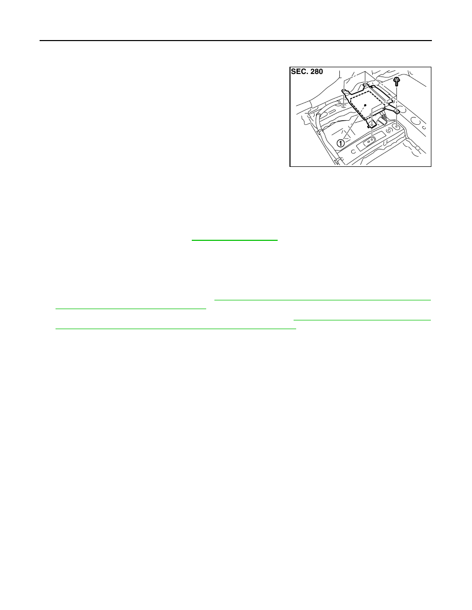
AROUND VIEW MONITOR CONTROL UNIT
AROUND VIEW MONITOR CONTROL UNIT
Exploded View
INFOID:0000000003528834
Removal and Installation
INFOID:0000000003528835
REMOVAL
1.
Remove front seat (LH side). Refer to
.
2.
Remove floor carpet. Keep a service area.
3.
Remove around view monitor control unit.
INSTALLATION
1.
Installation is the reverse order of removal.
2.
Perform camera image calibration. Refer to
AV-438, "CALIBRATING CAMERA IMAGE (AROUND VIEW
MONITOR) : Special Repair Requirement"
.
3.
Perform predicted course line center position adjustment. Refer to
AV-437, "PREDICTED COURSE LINE
CENTER POSITION ADJUSTMENT : Special Repair Requirement"
CAUTION:
Perform the calibration and perform the writing to the around view monitor control unit when remov-
ing and replacing each camera, removing the camera mounting parts (front grille, door mirror, etc.)
and replacing the around view monitor control unit.
JPNIA0898ZZ
1.
Around view monitor control unit
AV
REAR VIEW CAMERA
AV-923
< ON-VEHICLE REPAIR >
[BOSE AUDIO WITH NAVIGATION]
C
D
E
F
G
H
I
J
K
L
M
B
A
O
P
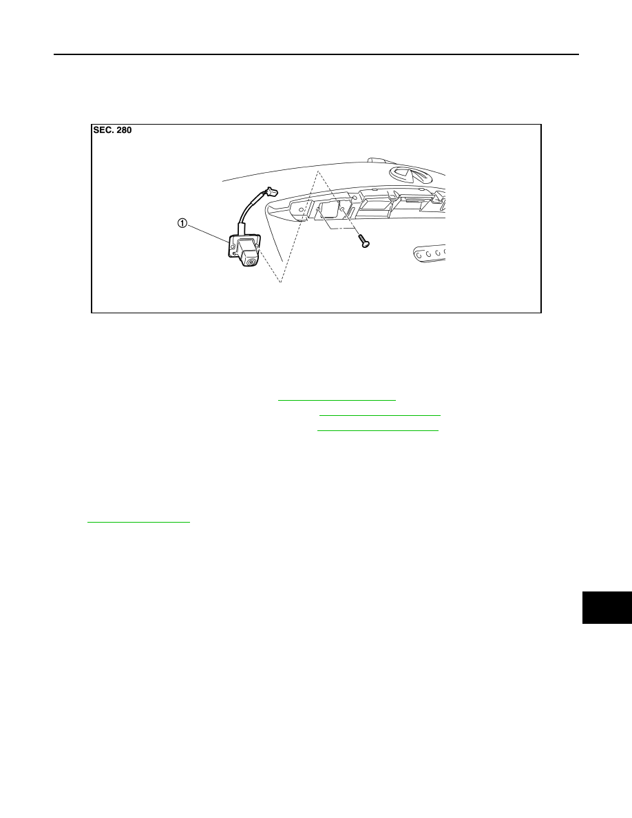
REAR VIEW CAMERA
Exploded View
INFOID:0000000003160804
DISASSEMBLY
Removal and Installation
INFOID:0000000003160805
REMOVAL
1.
Remove back door finisher inner. Refer to
2.
Remove back door outside finisher upper. Refer to
3.
Remove back door outside finisher lower. Refer to
.
4.
Remove rear view camera mounting screws and rear view camera harness connector.
5.
Remove rear view camera.
INSTALLATION
1.
Installation is the reverse order of removal.
2.
Adjust the guide line position if the guide line position is shifted after installing the rear view camera. Refer
to
.
JPNIA0884ZZ
1.
Rear view camera
AV-924
< ON-VEHICLE REPAIR >
[BOSE AUDIO WITH NAVIGATION]
REAR VIEW CAMERA
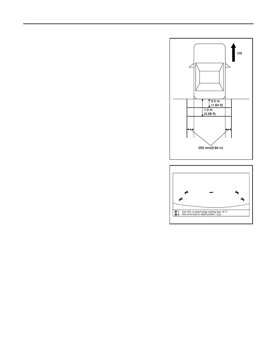
Adjustment
INFOID:0000000003160806
1.
Draw lines on rearward area of the vehicle passing through the
following points: 250 mm (9.84 in) from both sides of the vehicle,
and 0.5 m (1.64 ft), 1.0 m (3.28 ft) from the rear end of the
bumper.
2.
Set into “Adjust offset of rear view camera” mode of Confirma-
tion/Adjustment mode.
3.
Rotate the center dial, and then select the guiding line pattern so
that its angle is aligned with the correction line of the rear of the
vehicle.
4.
Make fine adjustment to the correction line of the rear of the
vehicle with up/down/left/right switches so that its position is
aligned with the guiding line. Press “”
CAUTION:
Never operate other function such as pressing BACK while writing index data.
If Confirmation/Adjustment mode does not function in the above procedure, perform one of the
following service to adjust the index again.
• Remove battery for five min. Then reconnect battery.
• Remove camera control unit connector for five min. Then reconnect camera control unit connec-
tor.
JPNIA0967GB
Selected pattern
: 7
Up/Down adjustment range
:
−
20 – 20
Left/Right adjustment range
:
−
20 – 20
SKIB3689E
Нет комментариевНе стесняйтесь поделиться с нами вашим ценным мнением.
Текст