Infiniti EX35. Manual — part 563
DLN-202
< DISASSEMBLY AND ASSEMBLY >
[REAR FINAL DRIVE: R200]
DRIVE PINION
12. Install differential case assembly. Refer to
.
CAUTION:
Never install rear cover at this timing.
13. Check and adjust drive gear runout, tooth contact, drive gear to drive pinion backlash, and companion
flange runout. Refer to
.
Recheck above items. Readjust the above description, if necessary.
14. Check total preload torque. Refer to
.
15. Install rear cover. Refer to
AWD : Adjustment
INFOID:0000000003135849
PINION GEAR HEIGHT
1.
Make sure all parts are clean and that the bearings are well
lubricated.
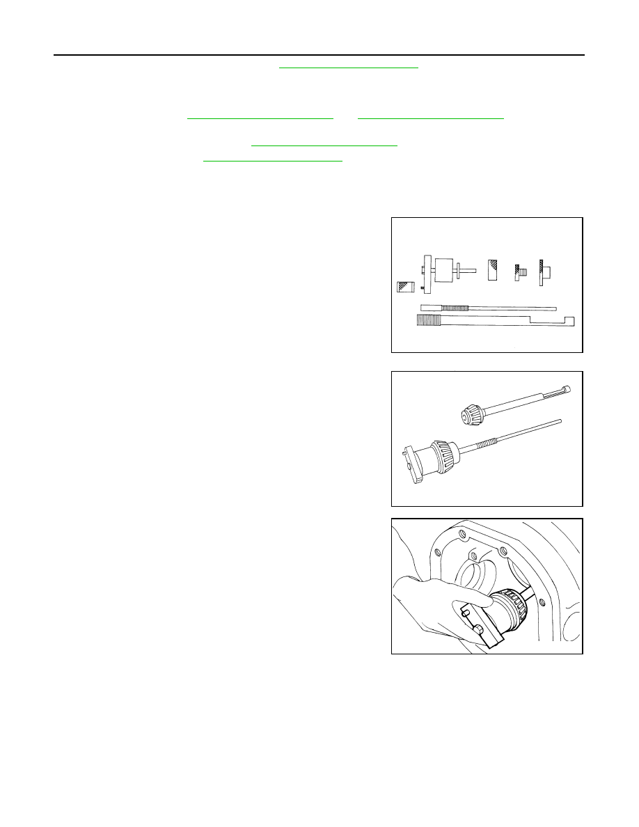
2.
Assemble the pinion gear bearings into the differential shim
selector tool [SST:
—
(J-34309)].
• Pinion front bearing; make sure the J-34309-3 pinion front
bearing seat is secured tightly against the J-34309-2 gauge
anvil. Then turn the pinion front bearing pilot, J-34309-5, to
secure the bearing in its proper position.
• Pinion rear bearing; the pinion rear bearing pilot, J-34309-8,
is used to center the pinion rear bearing only. The pinion rear
bearing locking seat, J-34309-4, is used to lock the bearing to
the assembly.
• Installation of J-34309-9 and J-34309-16; place a suitable
2.5 mm (0.098 in) thick plain washer between J-34309-9 and
J-34309-16. Both surfaces of J-34309-9 and J-34309-16 must
be parallel with a clearance of 2.5 mm (0.098 in).
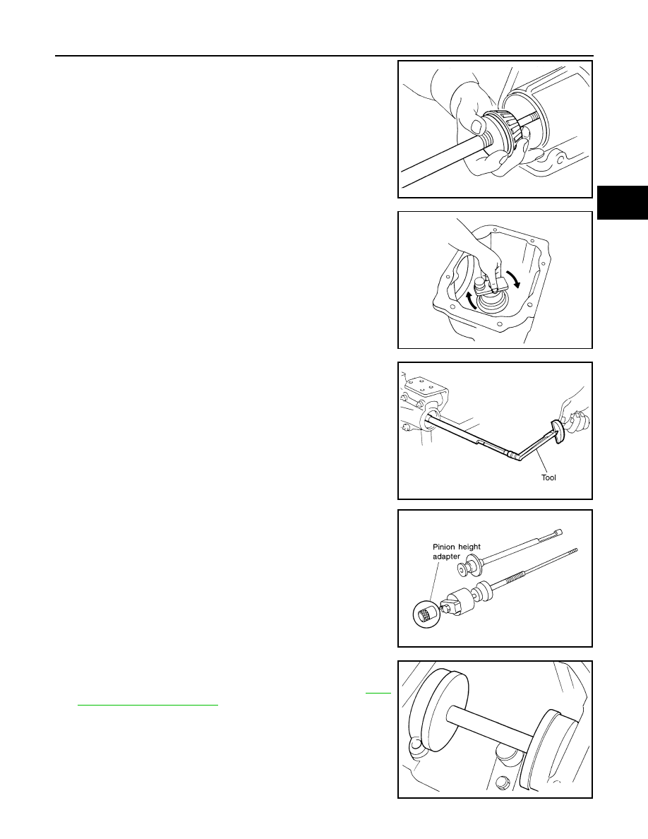
3.
Install the pinion rear bearing inner race into gear carrier. Then
place the pinion preload shim selector tool, J-34309-1, gauge
screw assembly.
SPD769
SPD197A
SPD893
DRIVE PINION
DLN-203
< DISASSEMBLY AND ASSEMBLY >
[REAR FINAL DRIVE: R200]
C
E
F
G
H
I
J
K
L
M
A
B
DLN
N
O
P
4.
Assemble the pinion front bearing inner race and the J-34309-2
gauge anvil. Assemble them together with the J-34309-1 gauge
screw in gear carrier. Make sure that the pinion height gauge
plate, J-34309-16, turns a full 360 degrees. Tighten the two sec-
tions together by hand.
5.
Turn the assembly several times to seat the bearings.
6.
Measure the turning torque at the end of the J-34309-2 gauge
anvil using preload gauge [SST: ST3127S000 (J-25765-A)].
7.
Place the J-34309-11 “R200A” pinion height adapter onto the
gauge plate and tighten it by hand.
CAUTION:
Make sure all machined surfaces are clean.
8.
Position the side bearing discs, J-25269-4, and arbor firmly into
the side bearing bores. Install the bearing caps and tighten bear-
ing cap mounting bolts to the specified torque. Refer to
SPD199A
SPD770
Standard
Turning torque specifica-
tion
: 1.0 – 1.3 N·m (0.11 – 0.13
kg-m, 9 – 11 in-lb)
PDIA0566E
SPD208A
SPD211A

DLN-204
< DISASSEMBLY AND ASSEMBLY >
[REAR FINAL DRIVE: R200]
DRIVE PINION
9.
Select the correct standard pinion height adjusting washer thick-
ness. Select by using a standard gauge of 3 mm (0.12 in) and J-
34309-101 feeler gauge. Measure the distance between the J-
34309-11 pinion height adapter including the standard gauge
and the arbor.
10. Write down exact measurement (the value of feeler gauge).
11. Correct the pinion height washer size by referring to the “pinion
head number”.
There are two numbers painted on the drive pinion. The first
one refers to the drive pinion and drive gear as a matched
set. This number should be the same as the number on the
drive gear. The second number is the “pinion head height
number”. It refers to the ideal pinion height from standard
for quietest operation. Use the following chart to determine
the correct pinion height washer.
12. Select the correct pinion height adjusting washer.
SPD204A
SPD775
Pinion head height number
Add or remove from the standard pinion height ad-
justing washer thickness measurement
−
6
−
5
−
4
−
3
−
2
−
1
0
+1
+2
+3
+4
+5
+6
Add 0.06 mm (0.0024 in)
Add 0.05 mm (0.0020 in)
Add 0.04 mm (0.0016 in)
Add 0.03 mm (0.0012 in)
Add 0.02 mm (0.0008 in)
Add 0.01 mm (0.0004 in)
Use the selected washer thickness
Subtract 0.01 mm (0.0004 in)
Subtract 0.02 mm (0.0008 in)
Subtract 0.03 mm (0.0012 in)
Subtract 0.04 mm (0.0016 in)
Subtract 0.05 mm (0.0020 in)
Subtract 0.06 mm (0.0024 in)
SPD542
DRIVE PINION
DLN-205
< DISASSEMBLY AND ASSEMBLY >
[REAR FINAL DRIVE: R200]
C
E
F
G
H
I
J
K
L
M
A
B
DLN
N
O
P
13. Remove the J-34309 differential shim selector tool from the final
drive housing. Then disassemble to retrieve the pinion bearings.
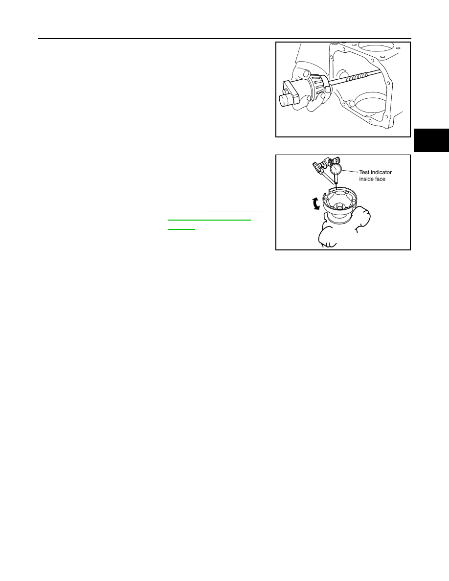
COMPANION FLANGE RUNOUT
1.
Fit a test indicator to the inner side of companion flange (socket
diameter).
2.
Rotate companion flange to check for runout.
3.
If the runout value is outside the runout limit, follow the proce-
dure below to adjust.
a.
Check for runout while changing the phase between companion flange and drive pinion by 90
°
step, and
search for the position where the runout is the minimum.
b.
If the runout value is still outside of the limit after the phase has been changed, possible cause will be an
assembly malfunction of drive pinion and pinion bearing and malfunction of pinion bearing. Check for
these items and repair if necessary.
c.
If the runout value is still outside of the limit after the check and repair, replace companion flange.
AWD : Inspection After Disassembly
INFOID:0000000003597237
DRIVE GEAR AND DRIVE PINION
• Clean up the disassembled parts.
• If the gear teeth never mesh or line-up correctly, determine the cause and adjust or replace as necessary.
• If the gears are worn, cracked, damaged, pitted or chipped (by friction) noticeably, replace with new drive
gear and drive pinion as a set.
BEARING
• Clean up the disassembled parts.
• If any chipped (by friction), pitted, worn, rusted or scratched marks, or unusual noise from the bearing is
observed, replace as a bearing assembly (as a new set).
SIDE GEAR AND PINION MATE GEAR
• Clean up the disassembled parts.
• If any cracks or damage on the surface of the tooth is found, replace.
• If any worn or chipped mark on the contact sides of the thrust washer is found, replace.
SIDE GEAR THRUST WASHER AND PINION MATE THRUST WASHER
• Clean up the disassembled parts.
• If it is chipped (by friction), damaged, or unusually worn, replace.
OIL SEAL
• Whenever disassembled, replace.
• If wear, deterioration of adherence (sealing force lips), or damage is detected on the lips, replace them.
DIFFERENTIAL CASE
• Clean up the disassembled parts.
• If any wear or crack on the contact sides of the differential case is found, replace.
SPD205A
Limit
Companion flange runout
: Refer to
PDIA0490E
Нет комментариевНе стесняйтесь поделиться с нами вашим ценным мнением.
Текст