Infiniti EX35. Manual — part 343

ABS ACTUATOR AND ELECTRIC UNIT (CONTROL UNIT)
BRC-87
< ECU DIAGNOSIS >
[VDC/TCS/ABS]
C
D
E
G
H
I
J
K
L
M
A
B
BRC
N
O
P
RR LH IN SOL
Operation status of each solenoid
valve
Actuator (solenoid valve) is active (“AC-
TIVE TEST” with CONSULT-III)
On
When the actuator (solenoid valve) is not
active and actuator relay is active (igni-
tion switch ON)
Off
RR LH OUT SOL
Operation status of each solenoid
valve
Actuator (solenoid valve) is active (“AC-
TIVE TEST” with CONSULT-III)
On
When the actuator (solenoid valve) is not
active and actuator relay is active (igni-
tion switch ON)
Off
MOTOR RELAY
Motor and motor relay operation
When the motor relay and motor are op-
erating
On
When the motor relay and motor are not
operating
Off
ACTUATOR RLY
(Note 2)
Actuator relay operation
When the actuator relay is operating
On
When the actuator relay is not operating
Off
ABS WARN LAMP
ABS warning lamp
(Note 3)
When ABS warning lamp is ON
On
When ABS warning lamp is OFF
Off
OFF LAMP
VDC OFF indicator lamp
(Note 3)
When VDC OFF indicator lamp is ON
On
When VDC OFF indicator lamp is OFF
Off
SLIP LAMP
SLIP indicator lamp
(Note 3)
When SLIP indicator lamp is ON
On
When SLIP indicator lamp is OFF
Off
EBD SIGNAL
EBD operation
EBD is active
On
EBD is inactive
Off
ABS SIGNAL
ABS operation
ABS is active
On
ABS is inactive
Off
TCS SIGNAL
TCS operation
TCS is active
On
TCS is inactive
Off
VDC SIGNAL
VDC operation
VDC is active
On
VDC is inactive
Off
EBD FAIL SIG
EBD fail-safe signal
In EBD fail-safe
On
EBD is normal
Off
ABS FAIL SIG
ABS fail-safe signal
In ABS fail-safe
On
ABS is normal
Off
TCS FAIL SIG
TCS fail-safe signal
In TCS fail-safe
On
TCS is normal
Off
VDC FAIL SIG
VDC fail-safe signal
In VDC fail-safe
On
VDC is normal
Off
CRANKING SIG
Crank operation
Crank is active
On
Crank is inactive
Off
USV [FL-RR]
(Note 2)
VDC switch-over valve
When actuator (switch-over valve) is ac-
tive (“ACTIVE TEST” with CONSULT-III)
On
When actuator (switch-over valve) is not
active and actuator relay is active (igni-
tion switch ON)
Off
Monitor item
Display content
Data monitor
Condition
Reference value in
normal operation

BRC-88
< ECU DIAGNOSIS >
[VDC/TCS/ABS]
ABS ACTUATOR AND ELECTRIC UNIT (CONTROL UNIT)
USV [FR-RL]
(Note 2)
VDC switch-over valve
When actuator (switch-over valve) is ac-
tive (“ACTIVE TEST” with CONSULT-III)
On
When actuator (switch-over valve) is not
active and actuator relay is active (igni-
tion switch ON)
Off
HSV [FL-RR]
(Note 2)
VDC switch-over valve
When actuator (switch-over valve) is ac-
tive (“ACTIVE TEST” with CONSULT-III)
On
When actuator (switch-over valve) is not
active and actuator relay is active (igni-
tion switch ON)
Off
HSV [FR-RL]
(Note 2)
VDC switch-over valve
When actuator (switch-over valve) is ac-
tive (“ACTIVE TEST” with CONSULT-III)
On
When actuator (switch-over valve) is not
active and actuator relay is active (igni-
tion switch ON)
Off
V/R OUTPUT
(Note 2)
Solenoid valve relay activated
When the solenoid valve relay is active
(When ignition switch OFF)
On
When the solenoid valve relay is not ac-
tive (in the fail-safe mode)
Off
M/R OUTPUT
Actuator motor and motor relay activat-
ed
When the actuator motor and motor relay
are active
(“ACTIVE TEST” with CONSULT-III)
On
When the actuator motor and motor relay
are inactive
Off
LDP) SHIFT POSITION
(Note 4)
Shift position
Shift position is not received
Off
Selector lever position
P/R/N/D
When using manual mode
MM 1st – MM 6th
LDP) ICC MAIN SW
(Note 4)
ICC main switch
ICC main switch is ON
On
ICC main switch is OFF
Off
LDP) LDP ON SW
(Note 4)
LDP ON switch
LDP ON switch is ON
On
LDP ON switch is OFF
Off
LDP) WIPER SIGNAL
(Note 4)
Front wiper operation
Front wiper is OFF.
Stop
Front wiper stops at fail-safe operation
PRTCT
Front wiper INT is operating.
1low
Front wiper LO is operating.
Low
Front wiper HI is operating.
High
LDP) TURN SIGNAL
(Note 4)
Turn signal operation
Turn signal is OFF.
Off
Turn signal lamp RH is blinking.
LH
Turn signal lamp LH is blinking.
RH
Turn signal lamp LH and RH are blinking.
LH&RH
LDP) STOP LMP SW
(Note 4)
Stop lamp switch signal status
When brake pedal is depressed
On
When brake pedal is not depressed
Off
LDP) BRAKE SW
(Note 4)
Brake switch signal status
When brake pedal is not depressed
On
When brake pedal is depressed
Off
LDP) LDW SW
(Note 4)
LDW switch condition
LDW switch is ON
(LDW ON indicator is ON)
On
LDW switch is OFF
(LDW ON indicator is OFF)
Off
Monitor item
Display content
Data monitor
Condition
Reference value in
normal operation

ABS ACTUATOR AND ELECTRIC UNIT (CONTROL UNIT)
BRC-89
< ECU DIAGNOSIS >
[VDC/TCS/ABS]
C
D
E
G
H
I
J
K
L
M
A
B
BRC
N
O
P
NOTE:
• 1: Confirm tire pressure is normal.
• 2: A brief moment of On/Off condition occurs every 20 seconds after ignition switch turned ON. This is not malfunction because it is an
operation for checking.
• 3: On and off timing for warning lamp and indicator lamp.
.
- Brake warning lamp: Refer to
- VDC OFF indicator lamp: Refer to
- SLIP indicator lamp: Refer to
- Lane departure warning lamp: Refer to
.
• 4: With LDP models.
BRC-90
< ECU DIAGNOSIS >
[VDC/TCS/ABS]
ABS ACTUATOR AND ELECTRIC UNIT (CONTROL UNIT)
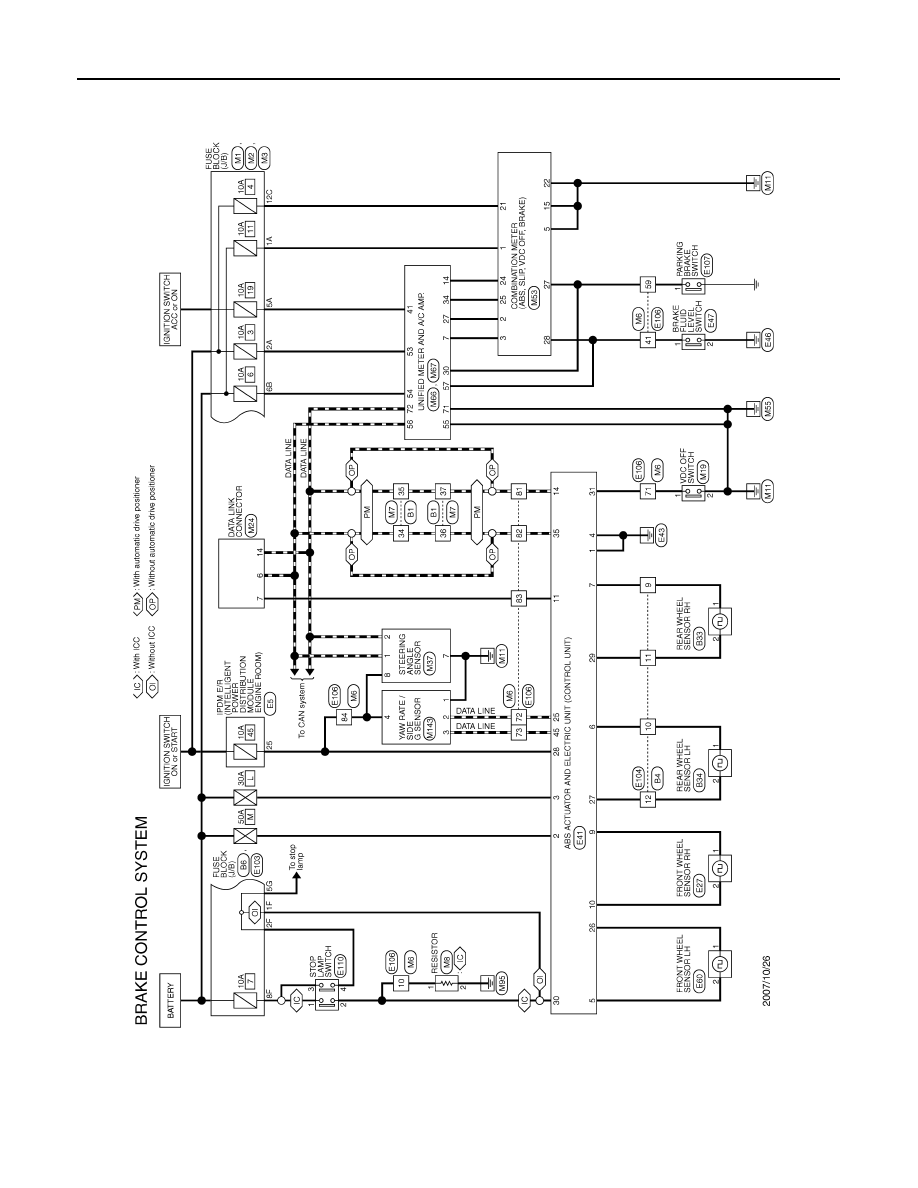
Wiring Diagram - BRAKE CONTROL SYSTEM -
INFOID:0000000003132985
JCFWM0118GB
Нет комментариевНе стесняйтесь поделиться с нами вашим ценным мнением.
Текст