Infiniti EX35. Manual — part 921
HAC-80
< COMPONENT DIAGNOSIS >
[AUTOMATIC AIR CONDITIONER]
BLOWER MOTOR
BLOWER MOTOR
WITHOUT LEFT AND RIGHT VENTILATION TEMPERATURE SEPARATELY
CONTROL SYSTEM
WITHOUT LEFT AND RIGHT VENTILATION TEMPERATURE SEPARATELY CON-
TROL SYSTEM : Description
INFOID:0000000003545615
COMPONENT DESCRIPTION
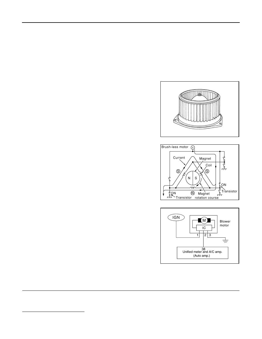
Brush-less Motor
The blower motor utilizes a brush-less motor with a rotating magnet.
Quietness is improved over previous motors where the brush was
the point of contact and the coil rotated.
Blower motor circuit
WITHOUT LEFT AND RIGHT VENTILATION TEMPERATURE SEPARATELY CON-
TROL SYSTEM : Component Function Check
INFOID:0000000003545616
1.
CONFIRM SYMPTOM BY PERFORMING THE FOLLOWING OPERATIONAL CHECK
1.
Turn fan control dial clockwise. Blower should operate on low speed.
2.
Turn fan control dial clockwise, and continue checking blower speed and fan symbol until all speeds
checked.
Is the inspection result normal?
YES
>> END.
RJIA2467J
ZHA152H
RJIA4071E
BLOWER MOTOR
HAC-81
< COMPONENT DIAGNOSIS >
[AUTOMATIC AIR CONDITIONER]
C
D
E
F
G
H
J
K
L
M
A
B
HAC
N
O
P
NO
>> Go to diagnosis procedure. Refer to
HAC-81, "WITHOUT LEFT AND RIGHT VENTILATION TEM-
PERATURE SEPARATELY CONTROL SYSTEM : Diagnosis Procedure"
WITHOUT LEFT AND RIGHT VENTILATION TEMPERATURE SEPARATELY CON-
TROL SYSTEM : Diagnosis Procedure
INFOID:0000000003545617
1.
PERFORM SELF-DIAGNOSIS STEP-4
Perform self-diagnosis STEP-4. Refer to
HAC-57, "WITHOUT LEFT AND RIGHT VENTILATION TEMPERA-
TURE SEPARATELY CONTROL SYSTEM : Diagnosis Description"
, see Nos. 1 to 5.
Does blower motor speed change according to each code No.?
YES
>> END.
NO
>> GO TO 2.
2.
CHECK POWER SUPPLY FOR BLOWER MOTOR
1.
Disconnect blower motor connector.
2.
Turn ignition switch ON.
3.
Check voltage between blower motor harness connector and ground.
Is the inspection result normal?
YES
>> GO TO 3.
NO
>> GO TO 6.
3.
CHECK BLOWER MOTOR GROUND CIRCUIT
1.
Turn ignition switch OFF.
2.
Check continuity between blower motor harness connector and ground.
Is the inspection result normal?
YES
>> GO TO 4.
NO
>> Repair harness or connector.
4.
CHECK CIRCUIT CONTINUITY BETWEEN BLOWER MOTOR AND UNIFIED METER AND A/C AMP.
1.
Disconnect unified meter and A/C amp. connector.
2.
Check continuity between blower motor harness connector and unified meter and A/C amp. harness con-
nector.
3.
Check continuity between blower motor harness connector and ground.
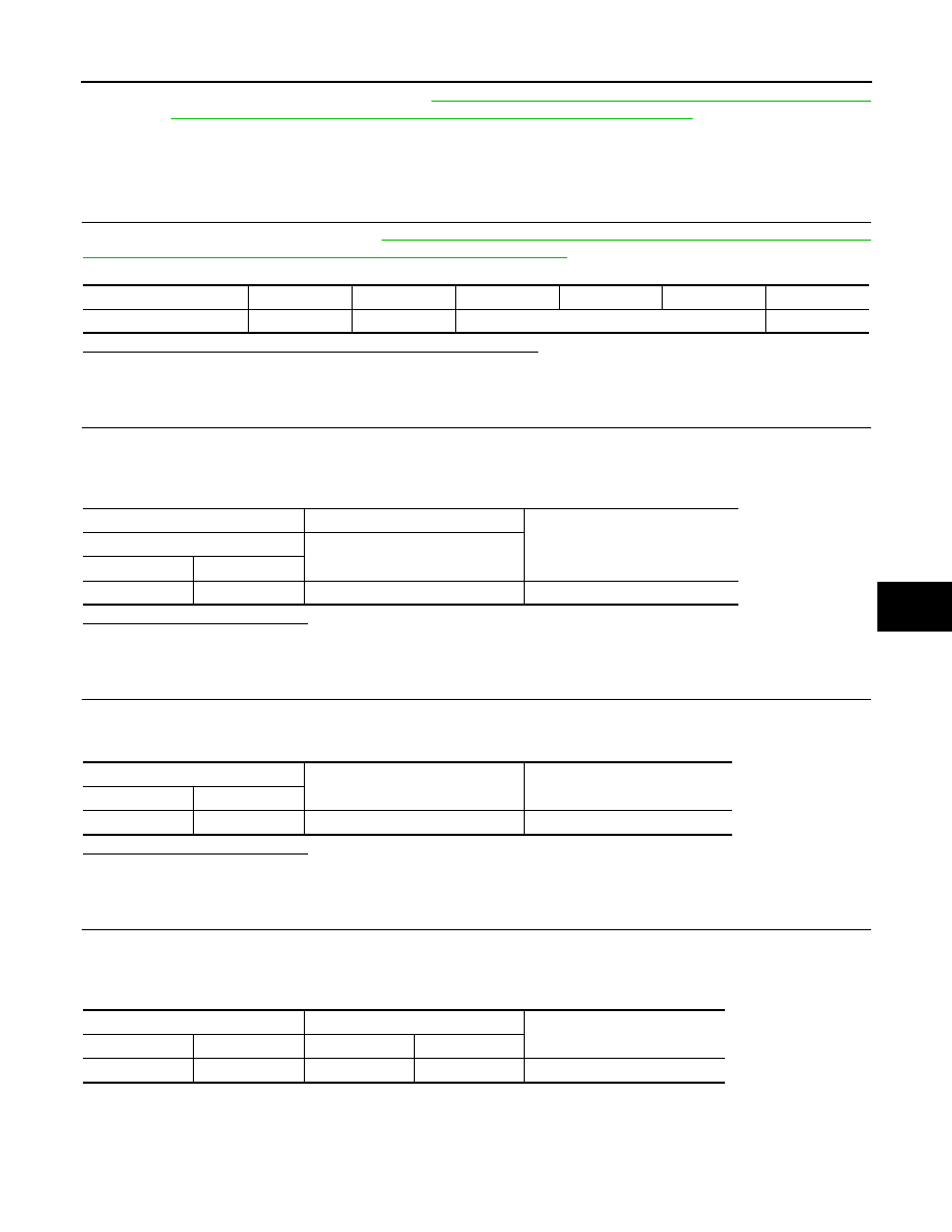
Code No.
41
42
43
44
45
46
Blower motor duty ratio
37%
91%
65%
91%
(+)
(
−
)
Voltage
Blower motor
—
Connector
Terminal
M109
1
Ground
Battery voltage
blower motor
—
Continuity
Connector
Terminal
M109
3
Ground
Existed
blower motor
Unified meter and A/C amp.
Continuity
Connector
Terminal
Connector
Terminal
M109
2
M66
38
Existed
HAC-82
< COMPONENT DIAGNOSIS >
[AUTOMATIC AIR CONDITIONER]
BLOWER MOTOR
Is the inspection result normal?
YES
>> GO TO 5.
NO
>> Repair harness or connector.
5.
CHECK UNIFIED METER AND A/C AMP. OUTPUT SIGNAL
1.
Reconnect blower motor connector and unified meter and A/C amp. connector.
2.
Turn ignition switch ON.
3.
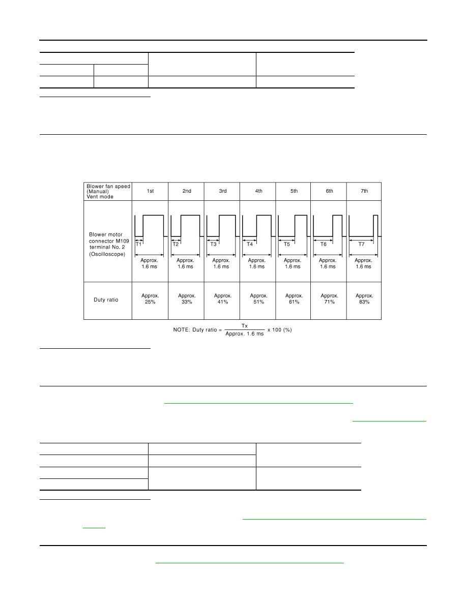
Set MODE switch to VENT position.
4.
Change fan speed from Lo to Hi, and check duty ratios between blower motor harness connector and
ground by using an oscilloscope. Normal terminal 2 drive signal duty ratios are shown in the table below.
Is the inspection result normal?
YES
>> Replace blower motor after confirming the fan air flow does not change.
NO
>> Replace unified meter and A/C amp.
6.
CHECK POWER VOLTAGE OF BLOWER RELAY
1.
Turn ignition switch OFF.
2.
Remove blower relay. Refer to
PG-98, "Fuse, Connector and Terminal Arrangement"
3.
Turn ignition switch ON.
4.
Check the voltage between blower relay fuse block terminals and ground. Refer to
for relay terminal assignment.
Is the inspection result normal?
YES
>> GO TO 7.
NO
>> Check ignition power supply circuit. Refer to
PG-51, "Wiring Diagram - IGNITION POWER SUP-
7.
CHECK BLOWER RELAY
1.
Turn ignition switch OFF.
2.
Install blower relay. Refer to
PG-98, "Fuse, Connector and Terminal Arrangement"
.
3.
Check operation sound of the blower relay after switching ignition switch ON.
blower motor
—
Continuity
Connector
Terminal
M109
2
ground
Not existed
JSIIA0068GB
(+)
(
−
)
Voltage
Blower relay
—
1
Ground
Battery voltage
3
BLOWER MOTOR
HAC-83
< COMPONENT DIAGNOSIS >
[AUTOMATIC AIR CONDITIONER]
C
D
E
F
G
H
J
K
L
M
A
B
HAC
N
O
P
Is the inspection result normal?
YES
>> GO TO 8.
NO
>> Replace blower relay.
8.
CHECK FUSE
Check fuse 15A [Nos 21 and 22, located in the fuse block (J/B). Refer to
PG-98, "Fuse, Connector and Termi-
Is the inspection result normal?
YES
>> Repair harness or connector.
NO
>> Be sure to eliminate cause of malfunction before installing new fuse.
WITHOUT LEFT AND RIGHT VENTILATION TEMPERATURE SEPARATELY CON-
TROL SYSTEM : Component Inspection
INFOID:0000000003545618
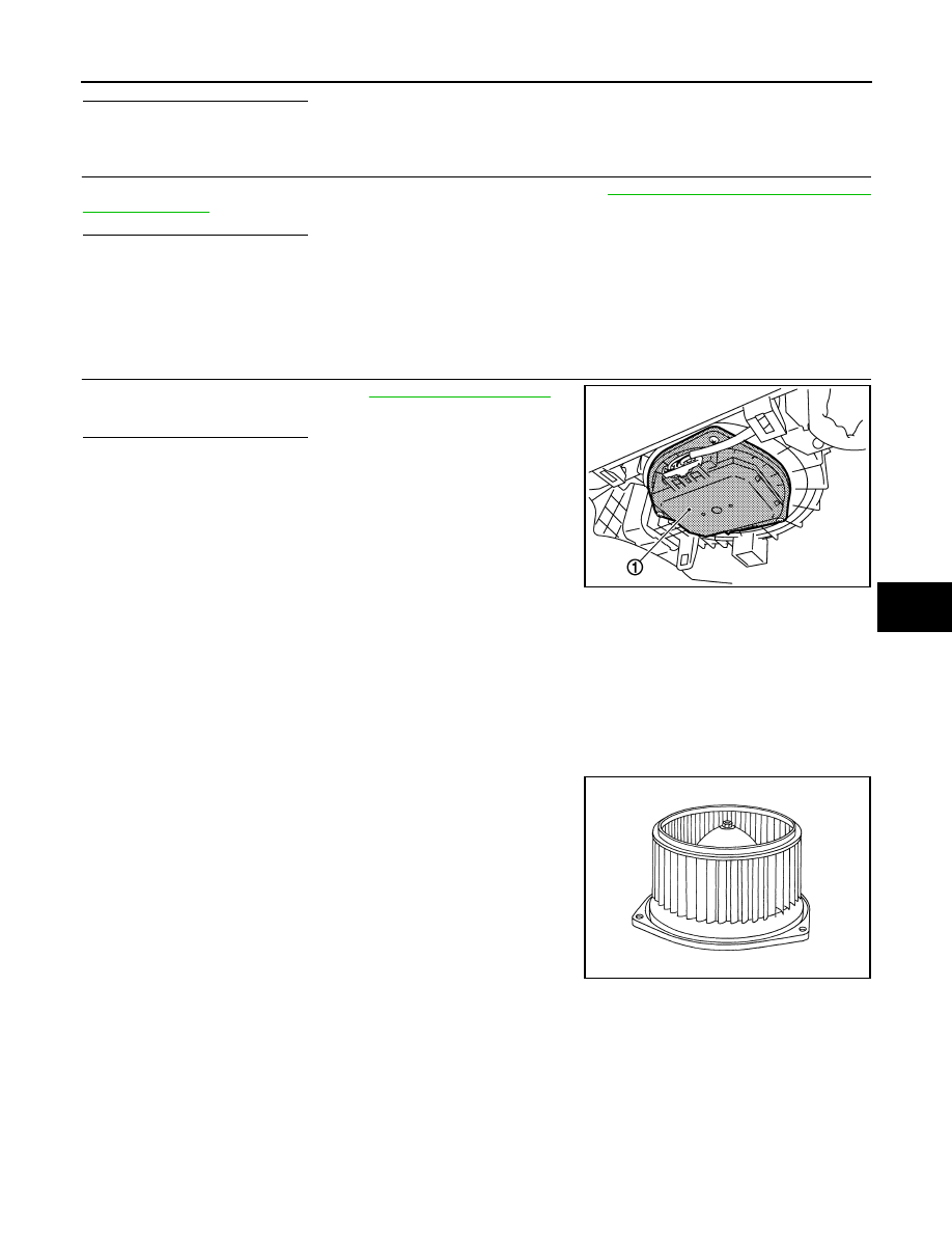
1.
CHECK BLOWER MOTOR
1.
Remove blower motor (1). Refer to
2.
Confirm smooth rotation of the blower motor.
Is the inspection result normal?
YES
>> END.
NO
>> Replace blower motor.
WITH LEFT AND RIGHT VENTILATION TEMPERATURE SEPARATELY CON-
TROL SYSTEM
WITH LEFT AND RIGHT VENTILATION TEMPERATURE SEPARATELY CONTROL
SYSTEM : Description
INFOID:0000000003545619
COMPONENT DESCRIPTION
Brush-less Motor
The blower motor utilizes a brush-less motor with a rotating magnet.
Quietness is improved over previous motors where the brush was
the point of contact and the coil rotated.
JSIIA1074ZZ
RJIA2467J
Нет комментариевНе стесняйтесь поделиться с нами вашим ценным мнением.
Текст