Infiniti EX35. Manual — part 682
EC-470
< COMPONENT DIAGNOSIS >
[VQ35HR]
POSITIVE CRANKCASE VENTILATION
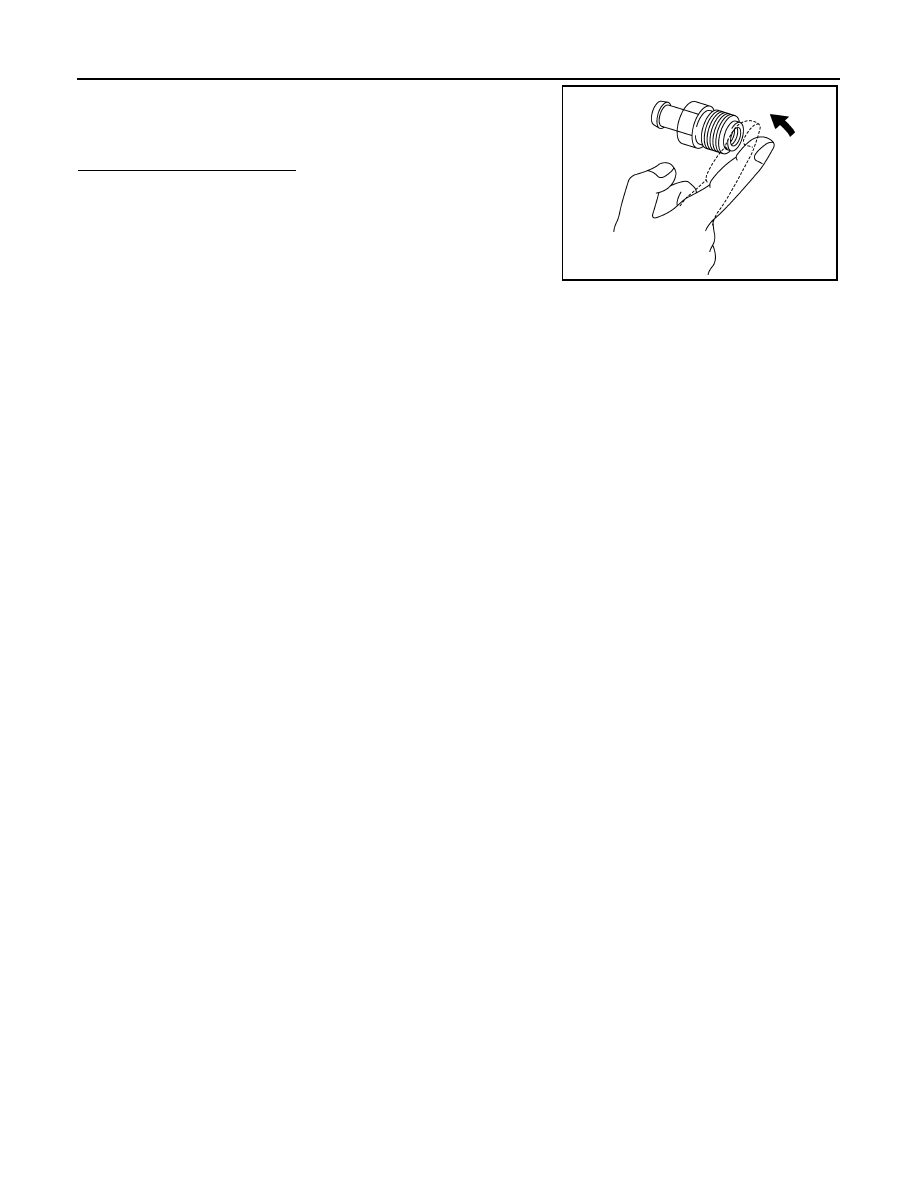
With engine running at idle, remove PCV valve from rocker cover. A
properly working valve makes a hissing noise as air passes through
it. A strong vacuum should be felt immediately when a finger is
placed over valve inlet.
Is the inspection result normal?
YES
>> INSPECTION END
NO
>> Replace PCV valve.
PBIB1589E

REFRIGERANT PRESSURE SENSOR
EC-471
< COMPONENT DIAGNOSIS >
[VQ35HR]
C
D
E
F
G
H
I
J
K
L
M
A
EC
N
P
O
REFRIGERANT PRESSURE SENSOR
Description
INFOID:0000000003133660
The refrigerant pressure sensor is installed at the condenser of the air conditioner system. The sensor uses an
electrostatic volume pressure transducer to convert refrigerant pressure to voltage. The voltage signal is sent
to ECM, and ECM controls cooling fan system.
Component Function Check
INFOID:0000000003133661
1.
CHECK REFRIGERANT PRESSURE SENSOR FUNCTION
1.
Start engine and warm it up to normal operating temperature.
2.
Turn A/C switch and blower fan switch ON.
3.
Check the voltage between ECM harness connector terminals under the following conditions.
Is the inspection result normal?
YES
>> INSPECTION END
NO
>> Go to
Diagnosis Procedure
INFOID:0000000003133662
1.
CHECK GROUND CONNECTION
1.
Turn A/C switch and blower fan switch OFF.
2.
Turn ignition switch OFF.
3.
Check ground connection M95. Refer to Ground Inspection in
Is the inspection result normal?
YES
>> GO TO 2.
NO
>> Repair or replace ground connection.
2.
CHECK REFRIGERANT PRESSURE SENSOR POWER SUPPLY CIRCUIT
1.
Disconnect refrigerant pressure sensor harness connector.
2.
Turn ignition switch ON.
3.
Check the voltage between refrigerant pressure sensor harness connector and ground.
Is the inspection result normal?
YES
>> GO TO 4.
NO
>> GO TO 3.
PBIB2657E
ECM
Voltage (V)
Connector
+
–
Terminal
Terminal
M107
105
(Refrigerant pressure sensor signal)
116
1.0 - 4.0
Refrigerant pressure sensor
Ground
Voltage (V)
Connector
Terminal
E77
3
Ground
Approx. 5

EC-472
< COMPONENT DIAGNOSIS >
[VQ35HR]
REFRIGERANT PRESSURE SENSOR
3.
DETECT MALFUNCTIONING PART
Check the following.
• Harness connectors M6, E106
• Harness for open or short between ECM and refrigerant pressure sensor
>> Repair open circuit or short to ground or short to power in harness or connectors.
4.
CHECK REFRIGERANT PRESSURE SENSOR GROUND CIRCUIT FOR OPEN AND SHORT
1.
Turn ignition switch OFF.
2.
Disconnect ECM harness connector.
3.
Check the continuity between refrigerant pressure sensor harness connector and ECM harness connec-
tor.
4.
Also check harness for short to ground and short to power.
Is the inspection result normal?
YES
>> GO TO 6.
NO
>> GO TO 5.
5.
DETECT MALFUNCTIONING PART
Check the following.
• Harness connectors M6, E106
• Harness for open or short between ECM and refrigerant pressure sensor
>> Repair open circuit or short to ground or short to power in harness or connectors.
6.
CHECK REFRIGERANT PRESSURE SENSOR INPUT SIGNAL CIRCUIT FOR OPEN AND SHORT
1.
Check the continuity between refrigerant pressure sensor harness connector and ECM harness connec-
tor.
2.
Also check harness for short to ground and short to power.
Is the inspection result normal?
YES
>> GO TO 8.
NO
>> GO TO 7.
7.
DETECT MALFUNCTIONING PART
Check the following.
• Harness connectors M6, E106
• Harness for open or short between ECM and refrigerant pressure sensor
>> Repair open circuit or short to ground or short to power in harness or connectors.
8.
CHECK INTERMITTENT INCIDENT
GI-38, "Intermittent Incident"
Is the inspection result normal?
YES
>> Replace refrigerant pressure sensor.
NO
>> Repair or replace malfunctioning part.
Refrigerant pressure sensor
ECM
Continuity
Connector
Terminal
Connector
Terminal
E77
1
M107
116
Existed
Refrigerant pressure sensor
ECM
Continuity
Connector
Terminal
Connector
Terminal
E77
2
M107
105
Existed

SNOW MODE SWITCH
EC-473
< COMPONENT DIAGNOSIS >
[VQ35HR]
C
D
E
F
G
H
I
J
K
L
M
A
EC
N
P
O
SNOW MODE SWITCH
Description
INFOID:0000000003133663
The snow mode switch signal is sent to the “unified meter and A/C amp.” from the snow mode switch. The
“unified meter and A/C amp.” then sends the signal to the ECM by CAN communication line.
The snow mode is used for driving or starting the vehicle on snowy roads or slippery areas. If the snow mode
is activated, the vehicle speed will not be accelerated immediately than your original pedal in due to avoid the
vehicle slip. In other words, ECM controls the rapid engine torque change by controlling the electric throttle
control actuator operating speed.
Component Function Check
INFOID:0000000003133664
1.
CHECK SNOW MODE SWITCH FUNCTION
NOTE:
If DTC U1000 or U1001 are displayed, first perform the trouble diagnosis for DTC U1000, U1001. Refer
to
1.
Turn ignition switch ON.
2.
Select “SNOW MODE SW” in “DATA MONITOR” mode with CONSULT-III.
3.
Check “SNOW MODE SW” indication under the following conditions.
Is the inspection result normal?
YES
>> GO TO 2.
NO
>> Go to
2.
CHECK SNOW MODE INDICATOR FUNCTION
1.
Turn ignition switch ON.
2.
Check the snow mode indicator in the snow mode switch under the following condition.
Is the inspection result normal?
YES
>> INSPECTION END
NO
>> Go to
Diagnosis Procedure
INFOID:0000000003133665
1.
CHECK SNOW MODE SWITCH OVERALL FUNCTION-I
Confirm the malfunctioning circuit (snow mode switch or snow mode indicator). Refer to
Which circuit is related to the incident?
Snow mode switch>>GO TO 2.
Snow mode indicator>>GO TO 7.
2.
CHECK DTC WITH “UNIFIED METER AND A/C AMP.”
MWI-40, "CONSULT-III Function (METER/M&A)"
.
Is the inspection result normal?
YES
>> GO TO 3.
NO
>> Go to
3.
CHECK SNOW MODE SWITCH POWER SUPPLY CIRCUIT
Monitor item
Condition
Indication
SNOW MODE SW
Snow mode switch
ON
ON
OFF
OFF
Condition
Snow mode indicator
Snow mode switch
ON
ON
OFF
OFF
Нет комментариевНе стесняйтесь поделиться с нами вашим ценным мнением.
Текст