Infiniti EX35. Manual — part 1051

LU-10
< ON-VEHICLE MAINTENANCE >
OIL FILTER
3.
Screw oil filter manually until it touches the installation surface,
then tighten it by 2/3 turn (A). Or tighten to the specification.
Inspection
INFOID:0000000003134529
INSPECTION AFTER INSTALLATION
1.
Check the engine oil level. Refer to
.
2.
Start the engine, and check there is no leakage of engine oil.
3.
Stop the engine and wait for 10 minutes.
4.
Check the engine oil level, and adjust the level. Refer to
.
Oil filter:
: 17.7 N·m (1.8 kg-m, 13 ft-lb)
JPBIA0077ZZ
OIL FILTER BRACKET (AWD)
LU-11
< ON-VEHICLE REPAIR >
C
D
E
F
G
H
I
J
K
L
M
A
LU
N
P
O
ON-VEHICLE REPAIR
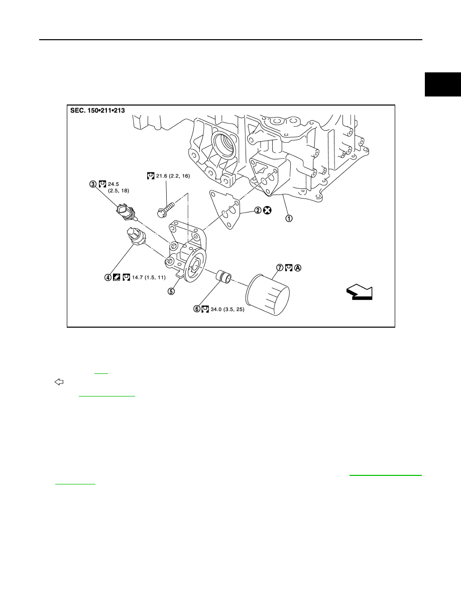
OIL FILTER BRACKET (AWD)
Exploded View
INFOID:0000000003134530
Removal and Installation
INFOID:0000000003134531
REMOVAL
WARNING:
Be careful not to get burn yourself, as engine oil may be hot.
1.
Remove engine undercover with power tool.
2.
Using the oil filter wrench [SST: KV10115801 (J38956)], remove oil filter. Refer to
.
CAUTION:
Never spill engine oil on drive belt.
3.
Disconnect oil pressure switch harness connector and oil temperature sensor harness connector.
4.
Remove oil filter bracket from oil pan (upper).
5.
Remove oil pressure switch and oil temperature sensor from oil filter bracket.
INSTALLATION
• Install oil pressure switch as follows:
- Remove old liquid gasket adhering to oil filter bracket.
- Apply liquid gasket and install oil pressure switch.
1.
Oil pan (upper)
2.
Gasket
3.
Oil temperature sensor
4.
Oil pressure switch
5.
Oil filter bracket
6.
Connector bolt
7.
Oil filter
A.
Refer to
: Engine front
Refer to
for symbols in the figure.
JPBIA1829GB
LU-12
< ON-VEHICLE REPAIR >
OIL FILTER BRACKET (AWD)
Use Genuine RTV Silicone Sealant or equivalent. Refer to
GI-15, "Recommended Chemical Products
Inspection
INFOID:0000000003134532
INSPECTION AFTER INSTALLATION
1.
Check the engine oil level and add engine oil. Refer to
2.
Start the engine, and check there is no leakage of engine oil.
3.
Stop the engine and wait for 10 minutes.
4.
Check the engine oil level again. Refer to
.
OIL PUMP
LU-13
< DISASSEMBLY AND ASSEMBLY >
C
D
E
F
G
H
I
J
K
L
M
A
LU
N
P
O
DISASSEMBLY AND ASSEMBLY
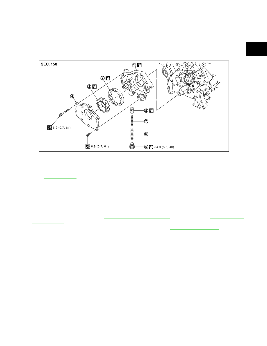
OIL PUMP
Exploded View
INFOID:0000000003134536
Disassembly and Assembly
INFOID:0000000003134539
DISASSEMBLY
1.
Remove oil pan (lower) and oil strainer. Refer to
(AWD models).
2.
Remove oil pan (upper). Refer to
(2WD models) or
(AWD models).
3.
Remove front timing chain case and timing chain (primary). Refer to
.
4.
Remove oil pump assembly.
5.
Remove oil pump cover.
6.
Remove oil pump inner rotor and oil pump outer rotor from oil pump body.
7.
After removing regulator valve plug, remove regulator valve spring and regulator valve.
ASSEMBLY
Note the following, and assemble in the reverse order of disassembly.
CAUTION:
Before assembly, apply new engine oil to the parts as instructed in the figure.
1.
Oil pump body
2.
Oil pump outer rotor
3.
Oil pump inner rotor
4.
Oil pump cover
5.
Regulator valve plug
6.
Regulator valve spring
7.
Regulator valve spring
8.
Regulator valve
Refer to
JPBIA0242GB
Нет комментариевНе стесняйтесь поделиться с нами вашим ценным мнением.
Текст