Infiniti EX35. Manual — part 332

C1110, C1153, C1170 ABS ACTUATOR AND ELECTRIC UNIT (CONTROL UNIT)
BRC-43
< COMPONENT DIAGNOSIS >
[VDC/TCS/ABS]
C
D
E
G
H
I
J
K
L
M
A
B
BRC
N
O
P
C1110, C1153, C1170 ABS ACTUATOR AND ELECTRIC UNIT (CONTROL
UNIT)
DTC Logic
INFOID:0000000003132890
DTC DETECTION LOGIC
DTC CONFIRMATION PROCEDURE
1.
DTC REPRODUCTION PROCEDURE
1.
Turn the ignition switch ON.
2.
Perform ABS actuator and electric unit (control unit) self-diagnosis.
Is DTC “C1110”, “C1153” or “C1170” detected?
YES
>> Proceed to diagnosis procedure. Refer to
.
NO
>> INSPECTION END
Diagnosis Procedure
INFOID:0000000003132891
1.
REPLACE ABS ACTUATOR AND ELECTRIC UNIT (CONTROL UNIT)
CAUTION:
Replace ABS actuator and electric unit (control unit) when self-diagnostic result shows items other
than those applicable.
>> Replace ABS actuator and electric unit (control unit).
Special Repair Requirement
INFOID:0000000003430136
1.
ADJUSTMENT OF STEERING ANGLE SENSOR NEUTRAL POSITION
Always perform the neutral position adjustment for the steering angle sensor, when replacing the ABS actua-
tor and electric unit (control unit). Refer to
BRC-8, "ADJUSTMENT OF STEERING ANGLE SENSOR NEU-
>> END
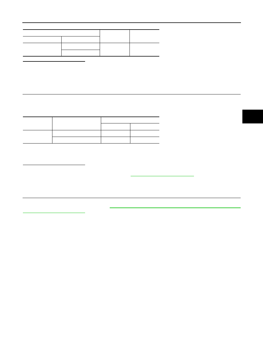
DTC
Display item
Malfunction detected condition
Possible cause
C1110
CONTROLLER FAILURE
When there is an internal malfunction in the ABS actuator
and electric unit (control unit).
ABS actuator and electric unit
(control unit)
C1153
EMERGENCY BRAKE
When ABS actuator and electric unit (control unit) is mal-
functioning. (Pressure increase is too much or too little)
C1170
VARIANT CODING
In a case where VARIANT CODING is different.

BRC-44
< COMPONENT DIAGNOSIS >
[VDC/TCS/ABS]
C1111 ABS MOTOR, MOTOR RELAY SYSTEM
C1111 ABS MOTOR, MOTOR RELAY SYSTEM
Description
INFOID:0000000003132893
PUMP
The pump returns the brake fluid stored in the reservoir to the master cylinder by reducing the pressure.
MOTOR
The motor drives the pump according to the signals transmitted by the ABS actuator and electric unit (control
unit).
MOTOR RELAY
Activates or deactivates motor according to the signals transmitted by the ABS actuator and electric unit (con-
trol unit).
DTC Logic
INFOID:0000000003132894
DTC DETECTION LOGIC
DTC CONFIRMATION PROCEDURE
1.
DTC REPRODUCTION PROCEDURE
1.
Turn the ignition switch ON.
2.
Perform ABS actuator and electric unit (control unit) self-diagnosis.
Is DTC “C1111” detected?
YES
>> Proceed to diagnosis procedure. Refer to
.
NO
>> INSPECTION END
Diagnosis Procedure
INFOID:0000000003132895
1.
CHECK CONNECTOR
1.
Turn the ignition switch OFF.
2.
Disconnect ABS actuator and electric unit (control unit) connector.
3.
Check terminal for deformation, disconnect, looseness, etc.
Is the inspection result normal?
YES
>> GO TO 2.
NO
>> Repair or replace damaged parts.
2.
CHECK ABS MOTOR AND MOTOR RELAY POWER SUPPLY CIRCUIT
Check the voltage between the ABS actuator and electric unit (control unit) harness connector and ground.
Is the inspection result normal?
YES
>> GO TO 3.
NO
>> Repair or replace damaged parts.
3.
CHECK ABS ACTUATOR AND ELECTRIC UNIT (CONTROL UNIT) GROUND CIRCUIT
Check the continuity between ABS actuator and electric unit (control unit) harness connector and ground.
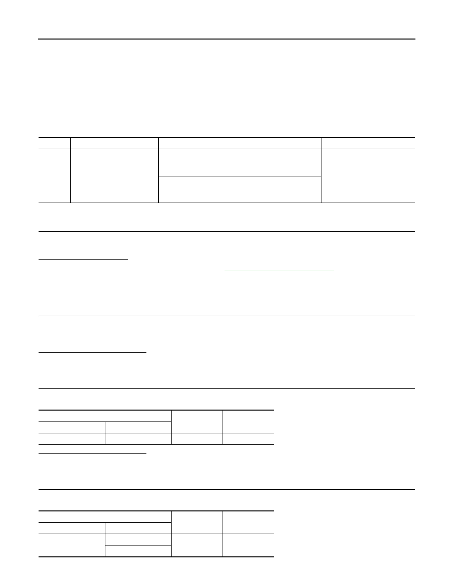
DTC
Display item
Malfunction detected condition
Possible cause
C1111
PUMP MOTOR
During the actuator motor operating with ON, when the
actuator motor turns OFF, or when the control line for ac-
tuator motor relay is open.
• Harness or connector
• ABS actuator and electric unit
(control unit)
During the actuator motor operating with OFF, when the
actuator motor turns ON, or when the control line for relay
is shorted to ground.
ABS actuator and electric unit (control unit)
—
Voltage
Connector
Terminal
E41
2
Ground
Battery voltage
C1111 ABS MOTOR, MOTOR RELAY SYSTEM
BRC-45
< COMPONENT DIAGNOSIS >
[VDC/TCS/ABS]
C
D
E
G
H
I
J
K
L
M
A
B
BRC
N
O
P
Is the inspection result normal?
YES
>> Replace ABS actuator and electric unit (control unit).
NO
>> Repair or replace damaged parts.
Component Inspection
INFOID:0000000003132896
1.
CHECK ACTIVE TEST
1.
On “ACTIVE TEST”, select “ABS MOTOR”.
2.
Touch “On” and “Off” on screen. Make sure motor relay and actuator relay operates as shown in table
below.
NOTE:
A brief moment of On/Off condition occurs every 20 seconds after ignition switch turned ON. This is not malfunction because it is
an operation for checking.
Is the inspection result normal?
YES
>> INSPECTION END
NO
>> Proceed to diagnosis procedure. Refer to
.
Special Repair Requirement
INFOID:0000000003430137
1.
ADJUSTMENT OF STEERING ANGLE SENSOR NEUTRAL POSITION
Always perform the neutral position adjustment for the steering angle sensor, when replacing the ABS actua-
tor and electric unit (control unit). Refer to
BRC-8, "ADJUSTMENT OF STEERING ANGLE SENSOR NEU-
>> END
ABS actuator and electric unit (control unit)
—
Continuity
Connector
Terminal
E41
1
Ground
Existed
4
Test item
Display item
Display
On
Off
ABS MOTOR
MOTOR RELAY
On
Off
ACTUATOR RLY (Note)
On
On
BRC-46
< COMPONENT DIAGNOSIS >
[VDC/TCS/ABS]
C1114 ACTUATOR RELAY SYSTEM
C1114 ACTUATOR RELAY SYSTEM
Description
INFOID:0000000003132898
Activates or deactivates each solenoid valve according to the signals transmitted by the ABS actuator and
electric unit (control unit).
DTC Logic
INFOID:0000000003132899
DTC DETECTION LOGIC
DTC CONFIRMATION PROCEDURE
1.
DTC REPRODUCTION PROCEDURE
1.
Turn the ignition switch ON.
2.
Perform ABS actuator and electric unit (control unit) self-diagnosis.
Is DTC “C1114” detected?
YES
>> Proceed to diagnosis procedure. Refer to
.
NO
>> INSPECTION END
Diagnosis Procedure
INFOID:0000000003132900
1.
CHECK CONNECTOR
1.
Turn the ignition switch OFF.
2.
Disconnect ABS actuator and electric unit (control unit) connector.
3.
Check terminal for deformation, disconnection, looseness, etc.
Is the inspection result normal?
YES
>> GO TO 2.
NO
>> Repair or replace damaged parts.
2.
CHECK SOLENOID, VDC SWITCH-OVER VALVE AND ACTUATOR RELAY POWER SUPPLY CIRCUIT
Check the voltage between ABS actuator and electric unit (control unit) harness connector and ground.
Is the inspection result normal?
YES
>> GO TO 3.
NO
>> Repair or replace damaged parts.
3.
CHECK SOLENOID, VDC SWITCH-OVER VALVE AND ACTUATOR RELAY GROUND CIRCUIT
Check the continuity between ABS actuator and electric unit (control unit) harness connector and ground.
DTC
Display item
Malfunction detected condition
Possible cause
C1114
MAIN RELAY
During the actuator relay operating with OFF, when the
actuator relay turns ON, or when the control line for the
relay is shorted to the ground.
• Harness or connector
• ABS actuator and electric unit
(control unit)
During the actuator relay operating with ON, when the
actuator relay turns ON, or when the control line for the
relay is open.
ABS actuator and electric unit (control unit)
—
Voltage
Connector
Terminal
E41
3
Ground
Battery voltage
ABS actuator and electric unit (control unit)
—
Continuity
Connector
Terminal
E41
1
Ground
Existed
4
Нет комментариевНе стесняйтесь поделиться с нами вашим ценным мнением.
Текст