Infiniti EX35. Manual — part 1414
TM-44
< FUNCTION DIAGNOSIS >
[5AT: RE5R05A]
DIAGNOSIS SYSTEM (TCM)
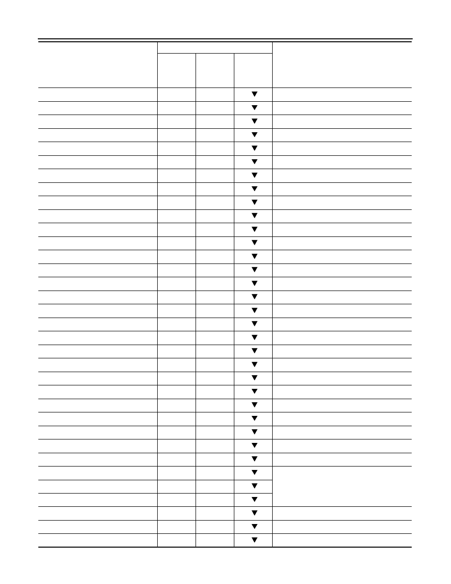
1ST POSI IND (On/Off)
—
—
—
MANU MODE IND (On/Off)
—
—
—
POWER M LAMP (On/Off)
—
—
Not mounted but displayed.
F-SAFE IND/L (On/Off)
—
—
—
ATF WARN LAMP (On/Off)
—
—
Not mounted but displayed.
BACK-UP LAMP (On/Off)
—
—
—
STARTER RELAY (On/Off)
—
—
—
PNP SW3 MON (On/Off)
—
—
—
C/V CLB ID1
—
—
—
C/V CLB ID2
—
—
—
C/V CLB ID3
—
—
—
UNIT CLB ID1
—
—
—
UNIT CLB ID2
—
—
—
UNIT CLB ID3
—
—
—
TRGT GR RATIO
—
—
—
TRGT PRES TCC (kPa)
—
—
—
TRGT PRES L/P (kPa)
—
—
—
TRGT PRES I/C (kPa)
—
—
—
TRGT PRE FR/B (kPa)
—
—
—
TRGT PRES D/C (kPa)
—
—
—
TRG PRE HLR/C (kPa)
—
—
—
SHIFT PATTERN
—
—
—
DRV CST JUDGE
—
—
—
START RLY MON
—
—
—
NEXT GR POSI
—
—
—
SHIFT MODE
—
—
—
MANU GR POSI
—
—
—
VEHICLE SPEED (km/h)
—
X
Vehicle speed recognized by the TCM.
1 POSITION SW (On/Off)
X
—
Not mounted but displayed.
OD CONT SW (On/Off)
X
—
HOLD SW (On/Off)
X
—
BRAKESW (On/Off)
X
—
Stop lamp switch
POWERSHIFT SW (On/Off)
X
—
Not mounted but displayed.
ASCD-OD CUT (On/Off)
—
—
—
Monitored item (Unit)
Monitor Item Selection
Remarks
ECU IN-
PUT SIG-
NALS
MAIN SIG-
NALS
SELEC-
TION
FROM
ITEM
DIAGNOSIS SYSTEM (TCM)
TM-45
< FUNCTION DIAGNOSIS >
[5AT: RE5R05A]
C
E
F
G
H
I
J
K
L
M
A
B
TM
N
O
P
DTC & SRT CONFIRMATION
DTC WORK SUPPORT
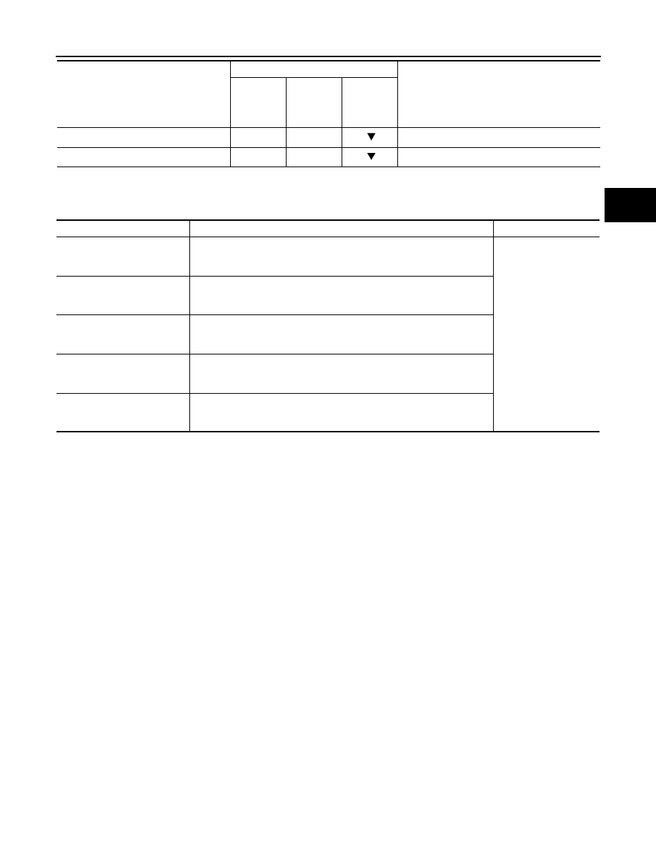
ASCD-CRUISE (On/Off)
—
—
—
DS RANGE (On/Off)
X
—
—
Monitored item (Unit)
Monitor Item Selection
Remarks
ECU IN-
PUT SIG-
NALS
MAIN SIG-
NALS
SELEC-
TION
FROM
ITEM
DTC WORK SUPPORT item
Description
Check item
1ST GR FNCTN P0731
Following items for “1st gear function” can be confirmed.
• Self-diagnosis status (whether the diagnosis is being performed or not)
• Self-diagnostic results (OK or NG)
• Input clutch solenoid
valve
• Front brake solenoid
valve
• Direct clutch solenoid
valve
• High and low reverse
clutch solenoid valve
• Each clutch and brake
• Hydraulic control cir-
cuit
2ND GR FNCTN P0732
Following items for “2nd gear function” can be confirmed.
• Self-diagnosis status (whether the diagnosis is being performed or not)
• Self-diagnostic results (OK or NG)
3RD GR FNCTN P0733
Following items for “3rd gear function” can be confirmed.
• Self-diagnosis status (whether the diagnosis is being performed or not)
• Self-diagnostic results (OK or NG)
4TH GR FNCTN P0734
Following items for “4th gear function” can be confirmed.
• Self-diagnosis status (whether the diagnosis is being performed or not)
• Self-diagnostic results (OK or NG)
5TH GR FNCTN P0735
Following items for “5th gear function” can be confirmed.
• Self-diagnosis status (whether the diagnosis is being performed or not)
• Self-diagnostic results (OK or NG)

TM-46
< COMPONENT DIAGNOSIS >
[5AT: RE5R05A]
U1000 CAN COMM CIRCUIT
COMPONENT DIAGNOSIS
U1000 CAN COMM CIRCUIT
Description
INFOID:0000000003130472
CAN (Controller Area Network) is a serial communication line for real-time application. It is an on-vehicle mul-
tiplex communication line with high data communication speed and excellent malfunction detection ability.
Many electronic control units are equipped onto a vehicle, and each control unit shares information and links
with other control units during operation (not independently). In CAN communication, control units are con-
nected with 2 communication lines (CAN-H line, CAN-L line) allowing a high rate of information transmission
with less wiring. Each control unit transmits/receives data but selectively reads required data only.
DTC Logic
INFOID:0000000003130473
DTC DETECTION LOGIC
DTC CONFIRMATION PROCEDURE
NOTE:
If “DTC CONFIRMATION PROCEDURE” has been previously performed, always turn ignition switch
OFF. Then wait at least 10 seconds before performing the next test.
1.
CHECK DTC DETECTION
With CONSULT-III
1.
Start the engine.
2.
Run engine for at least 6 consecutive seconds at idle speed.
3.
Select “Self Diagnostic Results” mode for “TRANSMISSION”.
With GST
Follow the procedure “With CONSULT-III”
Is “U1000 CAN COMM CIRCUIT” detected?
YES
>> Go to
NO
>> Check intermittent incident. Refer to
GI-38, "Intermittent Incident"
.
Diagnosis Procedure
INFOID:0000000003130474
1.
CHECK CAN COMMUNICATION CIRCUIT
With CONSULT-III
1.
Start the engine.
2.
Select “Self Diagnostic Results” mode for “TRANSMISSION”.
Is “U1000 CAN COMM CIRCUIT” detected?
YES
>> Go to LAN section. Refer to
LAN-18, "Trouble Diagnosis Flow Chart"
NO
>> Check intermittent incident. Refer to
GI-38, "Intermittent Incident"
.
DTC
Item
(CONSULT-III screen
terms)
A/T CHECK indicator
lamp judgment flicker
Diagnostic item is de-
tected when...
Possible cause
U1000
CAN COMM CIRCUIT
17th
TCM is not transmitting
or receiving CAN com-
munication signal for 2
seconds or more.
• Harness or connectors
(CAN communication
line is open or short-
ed.)
• TCM
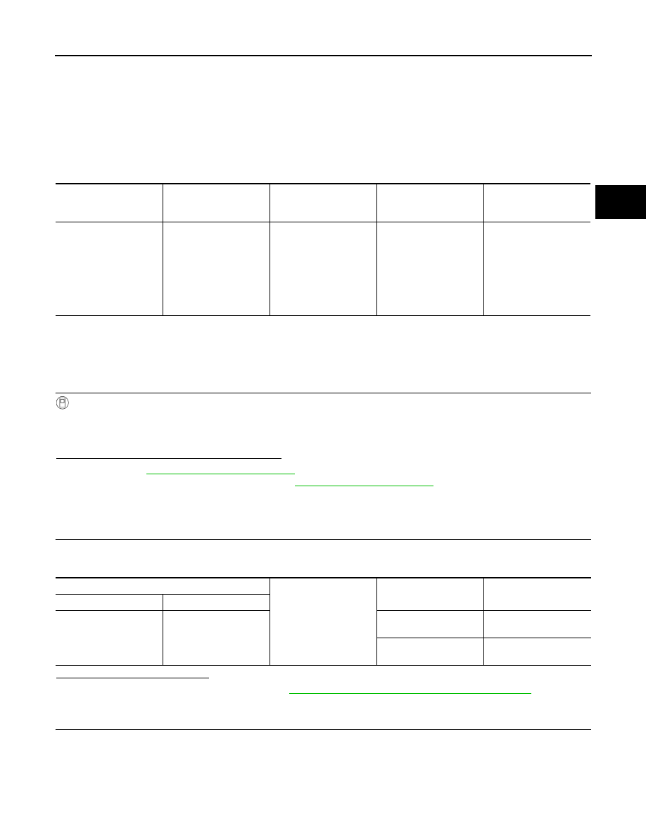
P0615 START SIGNAL
TM-47
< COMPONENT DIAGNOSIS >
[5AT: RE5R05A]
C
E
F
G
H
I
J
K
L
M
A
B
TM
N
O
P
P0615 START SIGNAL
Description
INFOID:0000000003130475
TCM prohibits cranking other than at “P” or “N” position.
DTC Logic
INFOID:0000000003130476
DTC DETECTION LOGIC
DTC CONFIRMATION PROCEDURE
NOTE:
If “DTC CONFIRMATION PROCEDURE” has been previously performed, always turn ignition switch
OFF. Then wait at least 10 seconds before performing the next test.
1.
CHECK DTC DETECTION
With CONSULT-III
1.
Shift the selector lever in “P” or “N” position.
2.
Turn ignition switch ON and wait for at least 2 seconds.
3.
Select “Self Diagnostic Results” mode for “TRANSMISSION”.
Is “P0615 STARTER RELAY/CIRC” detected?
YES
>> Go to
NO
>> Check intermittent incident. Refer to
GI-38, "Intermittent Incident"
.
Diagnosis Procedure
INFOID:0000000003130477
1.
CHECK STARTER RELAY SIGNAL
1.
Turn ignition switch ON.
2.
Check voltage between IPDM E/R connector terminal and ground.
Is the inspection result normal?
YES
>> Check starter relay circuit. Refer to
STR-9, "Wiring Diagram - STARTING SYSTEM -"
NO
>> GO TO 2.
2.
CHECK HARNESS BETWEEN A/T ASSEMBLY AND IPDM E/R (STEP 1)
1.
Turn ignition switch OFF.
2.
Disconnect A/T assembly harness connector and IPDM E/R connector.
3.
Check the continuity between A/T assembly vehicle side harness connector terminal and IPDM E/R vehi-
cle side harness connector terminal.
DTC
Item
(CONSULT-III screen
terms)
A/T CHECK indicator
lamp judgment flicker
Diagnostic item is de-
tected when...
Possible cause
P0615
STARTER RELAY/CIRC
14th
If this signal is ON other
than in “P” or “N” posi-
tion, this is judged to be a
malfunction.
(And if it is OFF in “P” or
“N” position, this too is
judged to be a malfunc-
tion.
• Harness or connectors
(Starter relay and TCM
circuit is open or short-
ed.)
• Starter relay circuit
IPDM E/R connector
Ground
Condition
Voltage (Approx.)
Connector
Terminal
E5
30
Selector lever in “P” and
“N” positions.
Battery voltage
Selector lever in other
positions.
0 V
Нет комментариевНе стесняйтесь поделиться с нами вашим ценным мнением.
Текст