Infiniti EX35. Manual — part 399

CCS
DIAGNOSIS SYSTEM (LANE CAMERA UNIT)
CCS-131
< FUNCTION DIAGNOSIS >
[LDW & LDP]
C
D
E
F
G
H
I
J
K
L
M
B
N
P
A
SELF DIAGNOSTIC RESULT
Displays memorized DTC in lane camera unit. Refer to
DATA MONITOR
ACTIVE TEST
CAUTION:
• Never perform the active test while driving.
• Active test cannot be started while the lane departure warning lamp is illuminated.
Departure steering
Steering wheel was steered more than the specified value in departure direction.
Evasive steering
Steering wheel was steered more than the specified value in the evasive direction.
R range
Selector lever was operated to R range.
Parking brake drift
Rear wheels lock was detected.
Not operating condition
Did not meet the operating condition (vehicle speed, turn signal operation, etc.).
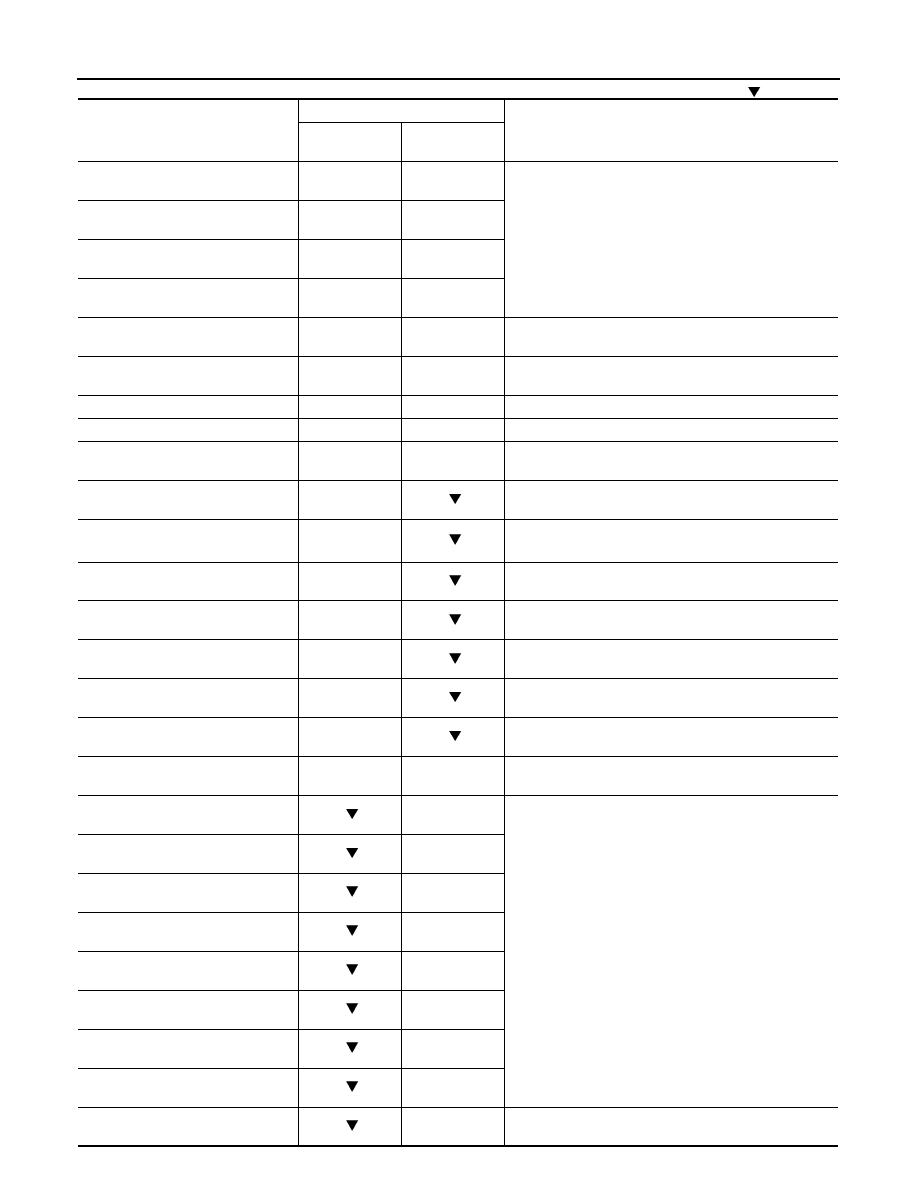
Monitored Item [unit]
Description
LDW SW
[On/Off]
Switch status judged from LDW switch signal
LDW ON LAMP
[On/Off]
Signal output status of LDW ON indicator
LDP ON IND
[On/Off]
Request signal status of LDP ON indicator lamp
LANE DPRT W/L
[On/Off]
Request signal status of lane departure warning lamp
BUZZER OUTPUT
[On/Off]
Signal output status of lane departure warning buzzer
LC INACCURAT
[On/Off]
Lane camera unit status
CAM HIGH TEMP
[On/Off]
Status of lane camera unit high temperature judgment
VHCL SPD SE
[km/h] or [mph]
Vehicle speed received from ABS actuator and electric unit (control unit) via CAN communi-
cation
TURN SIGNAL
[Off/LH/RH]
Status of “Turn signal” determined from BCM via CAN communication
LANE DETCT LH
[On/Off]
Left side lane marker detection
LANE DETCT RH
[On/Off]
Right side lane marker detection
CROSS LANE LH
[On/Off]
Condition that the vehicle is crossing left lane marker
CROSS LANE RH
[On/Off]
Condition that the vehicle is crossing right lane marker
WARN LANE LH
[On/Off]
Warning for left lane marker
WARN LANE RH
[On/Off]
Warning for right lane marker
VALID POS LH
[VLD/INVLD]
Lateral position for left lane marker is valid
VALID POS RH
[VLD/INVLD]
Lateral position for right lane marker is valid
AIMING DONE
[OK/NG]
Status that camera aiming is done
AIMING RESULT
[OK/NOK]
Result of camera aiming
XOFFSET
[pixel]
Lane camera unit installation condition
CHK AIM YAW
[deg]
Check result of camera aiming
CHK AIM ROLL
[deg]
Check result of camera aiming
CHK AIM PITCH
[deg]
Check result of camera aiming
FCTRY AIM YAW
[deg]
Lane camera unit installation condition
FCTRY AIM ROL
[deg]
Lane camera unit installation condition
FCTRY AIM PIT
[deg]
Lane camera unit installation condition
Active test item
Operation
Description
BUZZER DRIVE
On
Outputs the voltage to sound the lane departure warning buzzer.
Off
Stops the voltage to sound the lane departure warning buzzer.

CCS-132
< FUNCTION DIAGNOSIS >
[LDW & LDP]
DIAGNOSIS SYSTEM (LANE CAMERA UNIT)
NOTE:
“Active test” of indicator/warning lamp cannot be performed when applicable indicator/warning lamp is turned ON.
LDW ON IND
On
Outputs the voltage to illuminate the LDW ON indicator (on the LDW switch).
Off
Stops the voltage to illuminate the LDW ON indicator.
LDP ON IND
On
Requests the LDP ON indicator lamp ON [on the combination meter (Green)] to com-
bination meter (through unified meter and A/C amp.) via CAN communication.
Off
Stops the illumination request.
LANE DEPARTURE W/L
On
Requests the lane departure warning lamp ON [on the combination meter (Yellow)]
to combination meter (through unified meter and A/C amp.) via CAN communication.
Off
Stops the illumination request.
Active test item
Operation
Description

CCS
DIAGNOSIS SYSTEM [ABS ACTUATOR AND ELECTRIC UNIT (CONTROL
UNIT)]
CCS-133
< FUNCTION DIAGNOSIS >
[LDW & LDP]
C
D
E
F
G
H
I
J
K
L
M
B
N
P
A
DIAGNOSIS SYSTEM [ABS ACTUATOR AND ELECTRIC UNIT (CONTROL
UNIT)]
CONSULT-III Function
INFOID:0000000003554291
FUNCTION
CONSULT-III can display each diagnostic item using the diagnostic test modes shown following.
WORK SUPPORT
CAUTION:
Erase DTC memory of the lane camera unit after implementing work support. Refer to
SULT-III Function (LANE CAMERA)"
.
SELF DIAGNOSTIC RESULT
Operation Procedure
Before performing the self-diagnosis, start engine and drive vehicle at 30 km/h (19 MPH) or more for approxi-
mately 1 minute.
Display Item List
How to Erase Self-diagnosis Results
After erasing DTC memory, start the engine and drive the vehicle at 30 km/h (19 MPH) or more for approxi-
mately 1 minute as the final inspection, and make sure that the ABS warning lamp, VDC OFF indicator lamp,
SLIP indicator lamp and brake warning lamp turn OFF.
CAUTION:
If memory cannot be erased, perform applicable diagnosis.
NOTE:
• When the wheel sensor malfunctions, after inspecting the wheel sensor system, ABS warning lamp, VDC
OFF indicator lamp, SLIP indicator lamp and brake warning lamp will not turn OFF even when the system is
normal unless the vehicle is driven at approximately 30 km/h (19 MPH) or more for approximately 1 minute.
• Brake warning lamp will turn ON in case of parking brake operation (when switch is ON) or in case of brake
fluid level switch operation (when brake fluid is insufficient).
• VDC OFF switch should not stay in “ON” position.
DATA MONITOR
Display Item List
Diagnostic test mode
Function
Work support
This mode enables a technician to adjust some devices faster and more accurately by following
the indications on CONSULT-III.
Self diagnostic result
Self-diagnostic results can be read and erased quickly.
Data monitor
Input/Output data in the ABS actuator and electric unit (control unit) can be read.
Active test
CONSULT-III drives some actuators apart from ABS actuator and electric unit (control unit) and
also shifts some parameters in a specified range.
ECU identification
ABS actuator and electric unit (control unit) part number can be read.
Item
Description
ST ANG SEN ADJUSTMENT
Adjusts the neutral position of the steering angle sensor.
CCS-134
< FUNCTION DIAGNOSIS >
[LDW & LDP]
DIAGNOSIS SYSTEM [ABS ACTUATOR AND ELECTRIC UNIT (CONTROL
UNIT)]
×
: Applicable
: Optional item
Monitor item (Unit)
SELECT MONITOR ITEM
Remarks
ECU INPUT
SIGNALS
MAIN SIGNALS
FR LH SENSOR
[km/h (MPH)]
×
×
Wheel speed
FR RH SENSOR
[km/h (MPH)]
×
×
RR LH SENSOR
[km/h (MPH)]
×
×
RR RH SENSOR
[km/h (MPH)]
×
×
STOP LAMP SW
(On/Off)
×
×
Stop lamp switch signal status
BATTERY VOLT
(V)
×
×
Battery voltage supplied to the ABS actuator and electric
unit (control unit)
GEAR
×
×
Gear position determined by TCM
SLCT LVR POSI
×
×
A/T selector lever position
YAW RATE SEN
(d/s)
×
×
Yaw rate detected by yaw rate/side G sensor
ACCEL POS SIG
(%)
×
Throttle actuator opening/closing is displayed (Linked with
accelerator pedal)
SIDE G-SENSOR
(m/s
2
)
×
Transverse G detected by yaw rate/side G sensor
STR ANGLE SIG
(
°
)
×
Steering angle detected by steering angle sensor
PRESS SENSOR
(bar)
×
Brake fluid pressure detected by pressure sensor
ENGINE RPM
[tr/min (rpm)]
×
Engine speed
FLUID LEV SW
(On/Off)
×
Brake fluid level switch signal status
PARK BRAKE SW
(On/Off)
×
Parking brake switch signal status
LDP) APP SEN
(%) (Note 2)
×
×
Accelerator pedal position sensor status received from
ECM via CAN communication
FR RH IN SOL
(On/Off) (Note 1)
×
Operation status of each solenoid valve
FR RH OUT SOL
(On/Off) (Note 1)
×
FR LH IN SOL
(On/Off) (Note 1)
×
FR LH OUT SOL
(On/Off) (Note 1)
×
RR RH IN SOL
(On/Off) (Note 1)
×
RR RH OUT SOL
(On/Off) (Note 1)
×
RR LH IN SOL
(On/Off) (Note 1)
×
RR LH OUT SOL
(On/Off) (Note 1)
×
MOTOR RELAY
(On/Off)
×
Motor and motor relay operation
Нет комментариевНе стесняйтесь поделиться с нами вашим ценным мнением.
Текст