Infiniti EX35. Manual — part 965

COMBINATION METER
INL-97
< ECU DIAGNOSIS >
C
D
E
F
G
H
I
J
K
M
A
B
INL
N
O
P
DTC Index
INFOID:0000000003757124
Function
Specifications
Speedometer
Reset to zero by suspending communication.
Tachometer
Fuel gauge
Water temperature gauge
Illumination control
When suspending communication, change to nighttime mode.
Information display
The display turns off by suspending communication.
Buzzer
The buzzer turns off by suspending communication.
Warning lamp/indicator
lamp
ABS warning lamp
The lamp turns on by suspending communication.
VDC OFF indicator lamp
SLIP indicator lamp
Brake warning lamp
CRUISE warning lamp
High beam indicator
The lamp turns off by suspending communication.
Turn signal indicator lamp
Light indicator lamp
Oil pressure warning lamp
Malfunction indicator lamp
A/T CHECK warning lamp
AWD warning lamp
Low tire pressure warning lamp
Key warning lamp
AFS OFF indicator lamp
Lane departure warning lamp
LDP ON indicator lamp
Master warning lamp

INL-98
< SYMPTOM DIAGNOSIS >
INTERIOR LIGHTING SYSTEM SYMPTOMS
SYMPTOM DIAGNOSIS
INTERIOR LIGHTING SYSTEM SYMPTOMS
Symptom Table
INFOID:0000000003135173
CAUTION:
Perform the self-diagnosis with CONSULT-III before the symptom diagnosis. Perform the trouble diag-
nosis if any DTC is detected.
Symptom
Possible cause
Inspection item
All the following lamps do not turn ON.
• Map lamp
• Personal lamp
• Foot lamp
• Luggage room lamp
• Step lamp
• Vanity mirror lamp
• Harness between BCM and each
interior room lamp
• BCM
Interior room lamp power supply cir-
cuit
Refer to
• Interior room lamp does not turn ON even
though the door is open.
(It turns ON when turning the interior room
lamp ON.)
• Interior room lamp does not turn OFF even
though the door is closed.
• Harness between BCM and each
door switch
• Harness between BCM and each
interior room lamp
• BCM
Interior room lamp control circuit
Refer to
• Puddle lamp does not turn ON even though the
door is open.
• Puddle lamp does not turn OFF even though
the door is closed.
• Harness between BCM and each
door switch
• Harness between BCM and puddle
lamp
• BCM
Interior room lamp timer does not activate.
(It turns ON/ OFF when the door opens/closes.)
—
Check the interior room lamp setting.
Refer to
Step lamps (driver side and passenger side) do
not turn ON.
(The map lamp and the personal lamp turn ON.)
• Harness between BCM and each
step lamp
• BCM
Step lamps (driver side and passenger side) do
not turn OFF.
(The map lamp and the personal lamp turn OFF.)
Push-button ignition switch illumination does not
illuminate.
• Harness between BCM and push-
button ignition switch
• BCM
Push-button ignition switch illumina-
tion circuit
Refer to
Interior room lamp battery saver does not acti-
vate.
—
Check the interior room lamp battery
saver setting.
Refer to
PRECAUTIONS
INL-99
< PRECAUTION >
C
D
E
F
G
H
I
J
K
M
A
B
INL
N
O
P
PRECAUTION
PRECAUTIONS
Precaution for Supplemental Restraint System (SRS) "AIR BAG" and "SEAT BELT
PRE-TENSIONER"
INFOID:0000000003135174
The Supplemental Restraint System such as “AIR BAG” and “SEAT BELT PRE-TENSIONER”, used along
with a front seat belt, helps to reduce the risk or severity of injury to the driver and front passenger for certain
types of collision. This system includes seat belt switch inputs and dual stage front air bag modules. The SRS
system uses the seat belt switches to determine the front air bag deployment, and may only deploy one front
air bag, depending on the severity of a collision and whether the front occupants are belted or unbelted.
Information necessary to service the system safely is included in the “SRS AIRBAG” and “SEAT BELT” of this
Service Manual.
WARNING:
• To avoid rendering the SRS inoperative, which could increase the risk of personal injury or death in
the event of a collision which would result in air bag inflation, all maintenance must be performed by
an authorized NISSAN/INFINITI dealer.
• Improper maintenance, including incorrect removal and installation of the SRS, can lead to personal
injury caused by unintentional activation of the system. For removal of Spiral Cable and Air Bag
Module, see the “SRS AIRBAG”.
• Do not use electrical test equipment on any circuit related to the SRS unless instructed to in this
Service Manual. SRS wiring harnesses can be identified by yellow and/or orange harnesses or har-
ness connectors.
INL-100
< ON-VEHICLE REPAIR >
MAP LAMP
ON-VEHICLE REPAIR
MAP LAMP
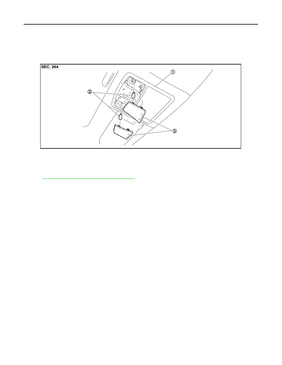
Exploded View
INFOID:0000000003135175
Removal and Installation
INFOID:0000000003135176
INT-26, "NORMAL ROOF : Exploded View"
for the map lamp assembly installation/removal.
Replacement
INFOID:0000000003135177
CAUTION:
• Disconnect the battery negative terminal or remove the fuse.
• Never touch the glass of bulb directly by hand. Keep grease and other oily matters away from it.
Never touch bulb by hand while it is lit or right after being turned off.
• Never leave bulb out of lamp reflector for a long time because dust, moisture smoke, etc. may affect
the performance of lamp. When replacing bulb, be sure to replace it with new one.
MAP LAMP BULB
1.
Insert any appropriate tool into the gap between the lens. Remove the lens.
2.
Remove the bulb.
1.
Map lamp assembly
2.
Bulb
3.
Lens
JPLIA0059ZZ
Нет комментариевНе стесняйтесь поделиться с нами вашим ценным мнением.
Текст