Infiniti EX35. Manual — part 414
CCS
PRECAUTIONS
CCS-191
< PRECAUTION >
[LDW & LDP]
C
D
E
F
G
H
I
J
K
L
M
B
N
P
A
PRECAUTION
PRECAUTIONS
Precaution for Supplemental Restraint System (SRS) "AIR BAG" and "SEAT BELT
PRE-TENSIONER"
INFOID:0000000003554306
The Supplemental Restraint System such as “AIR BAG” and “SEAT BELT PRE-TENSIONER”, used along
with a front seat belt, helps to reduce the risk or severity of injury to the driver and front passenger for certain
types of collision. This system includes seat belt switch inputs and dual stage front air bag modules. The SRS
system uses the seat belt switches to determine the front air bag deployment, and may only deploy one front
air bag, depending on the severity of a collision and whether the front occupants are belted or unbelted.
Information necessary to service the system safely is included in the “SRS AIRBAG” and “SEAT BELT” of this
Service Manual.
WARNING:
• To avoid rendering the SRS inoperative, which could increase the risk of personal injury or death in
the event of a collision which would result in air bag inflation, all maintenance must be performed by
an authorized NISSAN/INFINITI dealer.
• Improper maintenance, including incorrect removal and installation of the SRS, can lead to personal
injury caused by unintentional activation of the system. For removal of Spiral Cable and Air Bag
Module, see the “SRS AIRBAG”.
• Do not use electrical test equipment on any circuit related to the SRS unless instructed to in this
Service Manual. SRS wiring harnesses can be identified by yellow and/or orange harnesses or har-
ness connectors.
Precaution for LDW/LDP System Service
INFOID:0000000003514643
WARNING:
Be careful of traffic conditions and safety around the vehicle when performing road test.
CAUTION:
• Never use the LDP system when driving with free rollers or a chassis dynamometer.
• Never perform the active test while driving.
• Never disassemble and remodel the lane camera unit.
• Do not use the lane camera unit that is removed from the vehicle.
• Never change LDW initial state ON
⇒
OFF without the consent of the customer.
To keep the LDW/LDP system operating properly, be sure to observe the following items:
• Always keep the windshield clean. The sensing capability of the camera unit depends on the condi-
tion of the windshield. See “Appearance and care” for cleaning instructions.
• Never strike or damage the areas around the lane camera unit.
• Never touch the camera lens.
• Never attach a sticker (including transparent material) or install an accessory near the lane camera
unit.
• Never place reflective materials, such as a white paper or mirrors on the instrument panel. Reflection
of the sunlight may adversely affect the camera unit's lane marker detection capability.
CCS-192
< ON-VEHICLE REPAIR >
[LDW & LDP]
LANE CAMERA UNIT
ON-VEHICLE REPAIR
LANE CAMERA UNIT
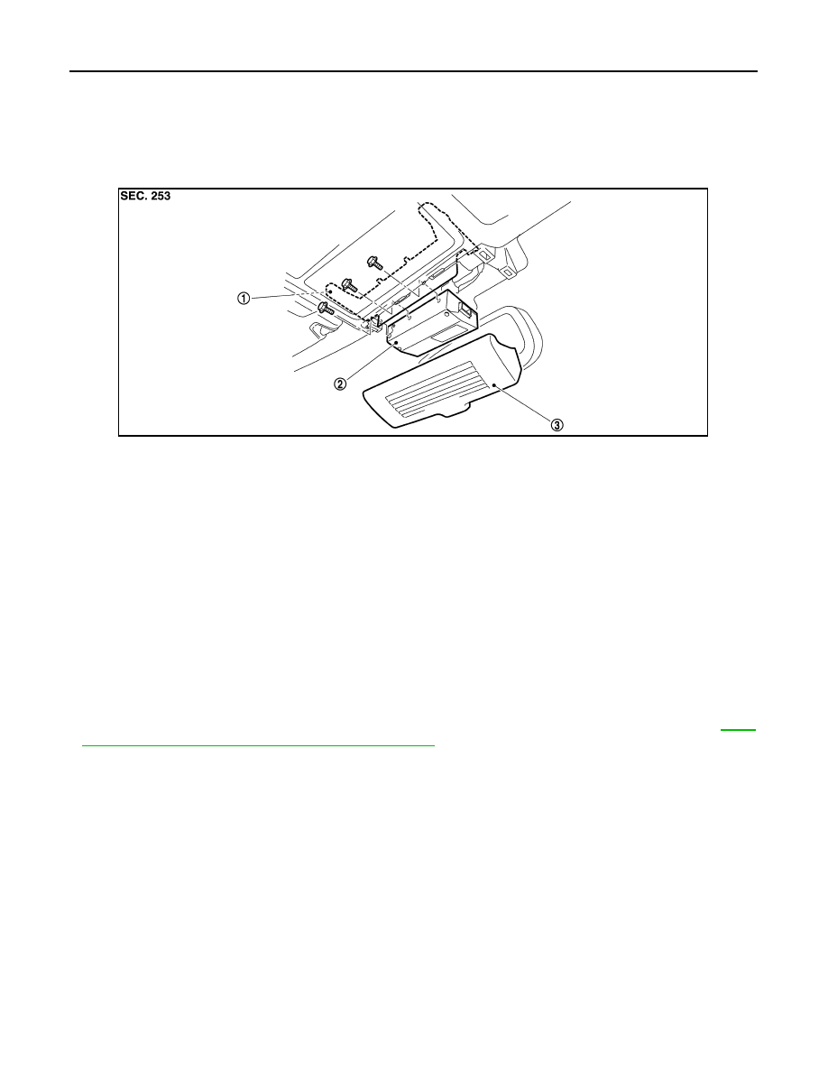
Exploded View
INFOID:0000000003514644
Removal and Installation
INFOID:0000000003514645
REMOVAL
1.
Remove the lane camera cover.
2.
Remove the bolts.
3.
Disconnect lane camera unit connector, and remove lane camera unit.
NOTE:
When replace the lane camera bracket, remove the headlining assembly.
INSTALLATION
Installation is the reverse order of removal.
CAUTION:
• Remove the camera lens cap for replacement.
• Never give an impact to the lane camera unit.
• Perform the camera aiming every time the lane camera unit is removed and installed. Refer to
112, "CAMERA AIMING ADJUSTMENT : Description"
1.
Lane camera bracket
2.
Lane camera unit
3.
Lane camera cover
JPOIA0123ZZ
CCS
LDW SWITCH
CCS-193
< ON-VEHICLE REPAIR >
[LDW & LDP]
C
D
E
F
G
H
I
J
K
L
M
B
N
P
A
LDW SWITCH
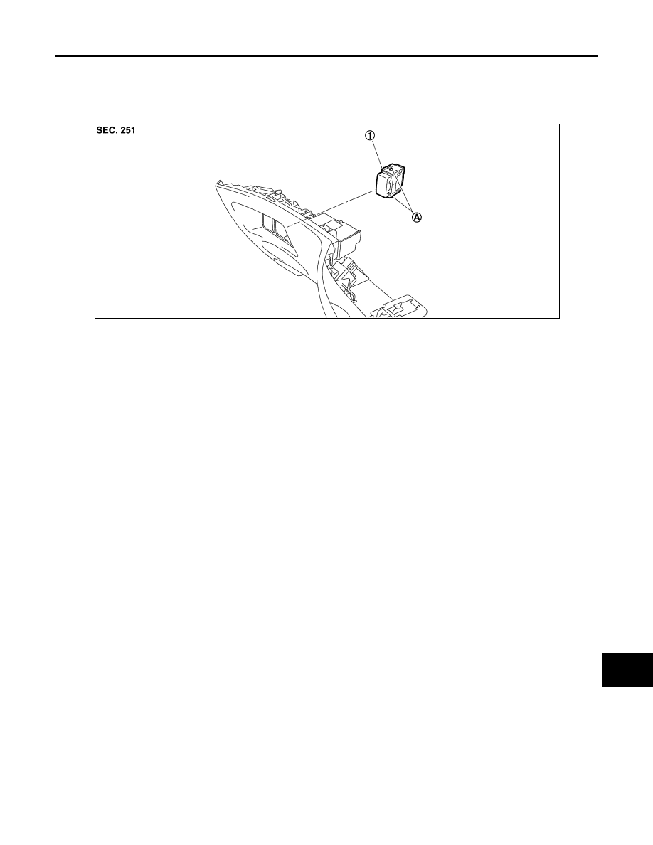
Exploded View
INFOID:0000000003514646
Removal and Installation
INFOID:0000000003514647
REMOVAL
1.
Remove the instrument driver lower panel. Refer to
.
2.
Disengage the pawl. Then remove LDW switch.
INSTALLATION
Install in the reverse order of removal.
1.
LDW switch
A.
Pawls
JPOIA0124ZZ
CCS-194
< ON-VEHICLE REPAIR >
[LDW & LDP]
LANE DEPARTURE WARNING BUZZER
LANE DEPARTURE WARNING BUZZER
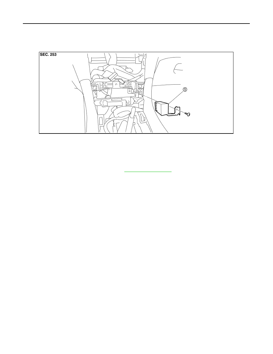
Exploded View
INFOID:0000000003514648
Removal and Installation
INFOID:0000000003514649
REMOVAL
1.
Remove the cluster lid C assembly. Refer to
.
2.
Remove the AV control unit.
3.
Remove the screw.
4.
Disconnect the connector. And remove lane departure warning buzzer.
INSTALLATION
Installation is the reverse order of removal.
1.
Lane departure warning buzzer
JPOIA0125ZZ
Нет комментариевНе стесняйтесь поделиться с нами вашим ценным мнением.
Текст