Infiniti EX35. Manual — part 1279
SEC-12
< FUNCTION DIAGNOSIS >
[INTELLIGENT KEY SYSTEM]
INTELLIGENT KEY SYSTEM/ENGINE START FUNCTION
• Press the push-button ignition switch 3 times or more within 1.5 seconds. (Emergency stop operation)
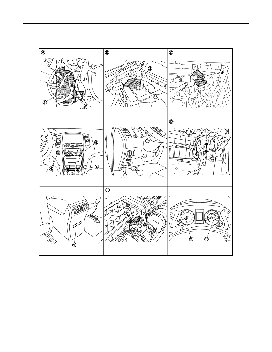
Component Parts Location
INFOID:0000000003586643
1.
BCM M118, M119, M121, M122, M123
2.
IPDM E/R E5, E6, E7
3.
Remote keyless entry receiver
M104
4.
Push-button ignition switch M50
5.
Unified meter and A/C amp. M66, M67 6.
Inside key antenna (instrument
center) M131
7.
Key slot M22
8.
ECM E107
9.
Inside key antenna (console)
M146
10. Inside key antenna (luggage room) B228 11.
Combination meter (KEY warning
lamp) M53
12. Combination meter (security indi-
cator) M53
A.
Dash side lower (passenger side)
B.
Engine room dash panel (RH)
C.
Behind the instrument assist low-
er panel
D.
Behind the instrument assist lower panel E.
Under the rear seat seatback
JMKIA2109ZZ
INTELLIGENT KEY SYSTEM/ENGINE START FUNCTION
SEC-13
< FUNCTION DIAGNOSIS >
[INTELLIGENT KEY SYSTEM]
C
D
E
F
G
H
I
J
L
M
A
B
SEC
N
O
P
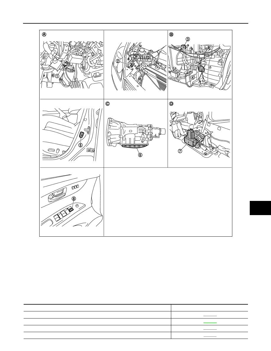
Component Description
INFOID:0000000003586644
1.
Stop lamp switch E110
2.
Hood switch E30
3.
Horn (high) E61, E62
4.
Horn (low) E69, E70
5.
Front door switch (driver side) B16
6.
TCM F151 (built into A/T assembly)
7.
Control device (detention switch)
M137
8.
Power window main switch (door
lock and unlock switch) D8, D9
A.
Behind the instrument driver lower
cover
B.
Behind the front bumper
C.
A/T assembly
D.
View with the center console assem-
bly removed
JMKIA2110ZZ
Component Reference
BCM
Steering lock unit
Push-button ignition switch
Door switch

SEC-14
< FUNCTION DIAGNOSIS >
[INTELLIGENT KEY SYSTEM]
INTELLIGENT KEY SYSTEM/ENGINE START FUNCTION
Control device (detention switch)
Inside key antenna
Remote keyless entry receiver
Stop lamp switch
Park/neutral position switch
Steering lock relay
Starter relay
Starter control relay
Security indicator
Key warning lamp
Component Reference
INFINITI VEHICLE IMMOBILIZER SYSTEM-NATS
SEC-15
< FUNCTION DIAGNOSIS >
[INTELLIGENT KEY SYSTEM]
C
D
E
F
G
H
I
J
L
M
A
B
SEC
N
O
P
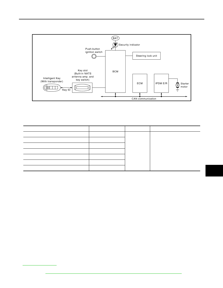
INFINITI VEHICLE IMMOBILIZER SYSTEM-NATS
System Diagram
INFOID:0000000003586645
System Description
INFOID:0000000003586646
INPUT/OUTPUT SIGNAL CHART
SYSTEM DESCRIPTION
• The IVIS (NATS) is an anti-theft system by registering an Intelligent Key ID in to the vehicle and prevents the
engine being started by an unregistered Intelligent Key. It has a higher protection against auto thefts that
duplicate mechanical key.
• It performs the ID verification when starting the engine in the same way as the Intelligent Key system. But, it
performs the IVIS (NATS) ID verification when inserting the Intelligent Key and performs the Intelligent Key
ID verification when carrying the Intelligent Key.
• The mechanical key integrated in the Intelligent Key cannot start the engine. When the Intelligent Key bat-
tery is discharged, the IVIS (NATS) ID verification memorized to the transponder integrated with Intelligent
Key is performed by inserting the Intelligent Key into the key slot. If the verification results are OK, the
engine start operation can be performed by the push-button ignition switch operation.
• Locate the security indicator and apply the anti-theft system equipment sticker, forewarn that the IVIS
(NATS) is onboard with the model.
• The security indicator always blinks when the power supply position is in LOCK and ACC position.
• Intelligent Key can be registered up to 4 keys (Including the standard ignition key) on request from the
owner.
• The specified registration is required when replacing ECM, BCM or Intelligent Key. The registrations proce-
dure for IVIS (NATS) and registration procedure for Intelligent Key when installing the BCM, refer to CON-
SULT-III Operation Manual NATS-IVIS/NVIS.
• Possible symptom of IVIS (NATS) malfunction is “Engine can not start”. The engine can be started with the
Intelligent Key system and IVIS (NATS). Identify the possible causes according to “Work Flow”, Refer to
• If ECM other than Genuine NISSAN is installed, the engine cannot be started. For ECM replacement proce-
dure, refer to
SEC-8, "ECM RE-COMMUNICATING FUNCTION : Special Repair Requirement"
.
JMKIA0058GB
Switch
Input signal to BCM
BCM function
Actuator
Push-button ignition switch
Push switch
IVIS (NATS)
• Steering lock relay
• Steering lock unit
• Starter relay (IPDM E/R)
• Starter control relay (IPDM E/R)
• Starter motor
• KEY warning lamp
• Security indicator lamp
Control device
P range
PNP switch
N, P range
Stop lamp switch
Brake ON/OFF
Key slot
Key ID
Each door switch
Door open/close
ECM
Engine status signal
Нет комментариевНе стесняйтесь поделиться с нами вашим ценным мнением.
Текст