Infiniti EX35. Manual — part 36
ADP-138
< ECU DIAGNOSIS >
DRIVER SEAT CONTROL UNIT
JCJWM0276GB
DRIVER SEAT CONTROL UNIT
ADP-139
< ECU DIAGNOSIS >
C
D
E
F
G
H
I
K
L
M
A
B
ADP
N
O
P
Fail Safe
INFOID:0000000003134777
The fail-safe mode may be activated if the following symptoms are observed.
JCJWM0277GB
ADP-140
< ECU DIAGNOSIS >
DRIVER SEAT CONTROL UNIT
DTC Index
INFOID:0000000003134778
*1
:
• 0: Current malfunction is present
• 1-39: Displayed if any previous malfunction is present when current condition is normal. The numeral value increases by one at each
IGN ON to OFF cycle from 1 to 39. The counter remains at 39 even if the number of cycles exceeds it. However, the counter is reset
to 1 if any malfunction is detected again, the normal operation is resumed and the ignition switch is turned from OFF to ON.
Operating in
fail-safe mode
Malfunction Item
Related
DTC
Diagnosis
Only manual functions operate normally.
CAN communication
U1000
Tilt sensor
B2118
Telescopic sensor
B2119
Detent switch
B2126
Only manual functions, except door mirror, operate normally.
UART communication
B2128
Only manual functions, except seat sliding, operate normally.
Seat sliding output
B2112
Only manual functions, except seat reclining, operate normally.
Seat reclining output
B2113
CONSULT-III
display
Timing
*1
Item
Reference page
Current mal-
function
Previous mal-
function
CAN COMM CIRCUIT
[U1000]
0
1-39
CAN communication
SEAT SLIDE
[B2112]
0
1-39
Seat slide motor output
SEAT RECLINING
[B2113]
0
1-39
Seat reclining motor output
TILT SENSOR
[B2118]
0
1-39
Tilt sensor input
TELESCO SENSOR
[B2119]
0
1-39
Telescopic sensor input
DETENT SW
[B2126]
0
1-39
Detention switch condition
UART COMM
[B2128]
0
1-39
UART communication

AUTOMATIC DRIVE POSITIONER CONTROL UNIT
ADP-141
< ECU DIAGNOSIS >
C
D
E
F
G
H
I
K
L
M
A
B
ADP
N
O
P
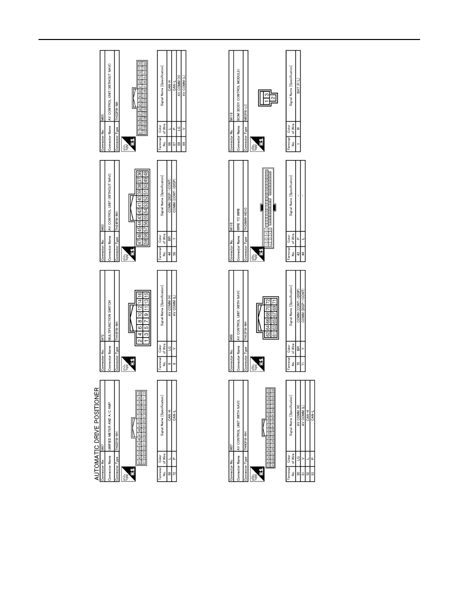
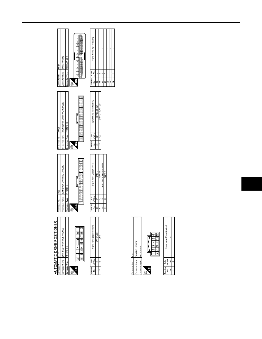
AUTOMATIC DRIVE POSITIONER CONTROL UNIT
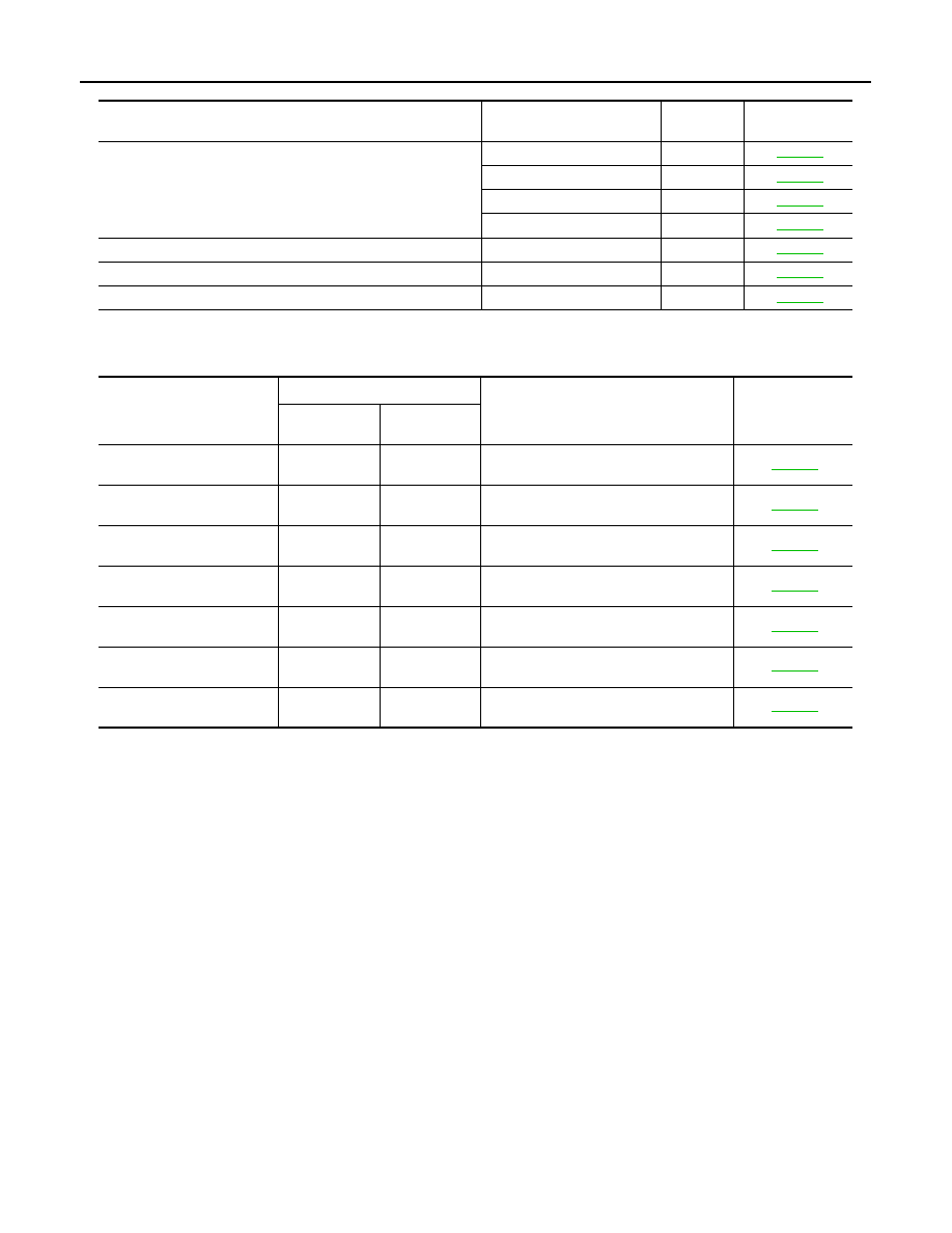
Reference Value
INFOID:0000000003134779
TERMINAL LAYOUT
PHYSICAL VALUES
JMJIA0199ZZ
Terminal No.
Wire
color
Description
Condition
Voltage (V)
(Approx.)
+
-
Signal name
Input/
Out-
put
1
Ground
Y
Tilt switch up signal
Input
Tilt switch
Operate
(up)
0
Other than
above
5
2
Ground
LG
Changeover switch RH
signal
Input
Changeover
switch position
RH
0
Neutral or
LH
5
3
Ground
G
Mirror switch up signal
Input
Mirror switch
Operated
(up)
0
Other than
above
5
4
Ground
V
Mirror switch left signal
Input
Mirror switch
Operated
(left)
0
Other than
above
5
5
Ground
R
Door mirror sensor (RH)
up/down signal
Input
Door mirror RH position
Change between 3.4 (close to
peak) 0.6 (close to valley)
6
Ground
GR
Door mirror sensor (LH)
up/down signal
Input
Door mirror LH position
Change between 3.4 (close to
peak) 0.6 (close to valley)
7
Ground
O
Tilt sensor signal
Input
Tilt position
Change between 1.2 (close to top)
3.4 (close to bottom)
9
Ground
L
Memory switch 1 signal
Input
Memory switch 1
Push
0
Other than
above
5
10
Ground
V
UART communication
(TX)
Out-
put
Ignition switch ON
JMJIA0118ZZ
Нет комментариевНе стесняйтесь поделиться с нами вашим ценным мнением.
Текст