Infiniti EX35. Manual — part 1437

TM-136
< SYMPTOM DIAGNOSIS >
[5AT: RE5R05A]
SYSTEM SYMPTOM
70
Others
Engine stall.
ON vehicle
1. A/T fluid level and state
2. Engine speed signal
3. Turbine revolution sensor
4. Torque converter clutch solenoid valve
5. CAN communication line
6. Control valve with TCM
OFF vehicle
7. Torque converter
71
Engine stalls when se-
lector lever shifted “N”
→
“D” or “R”.
ON vehicle
1. A/T fluid level and state
2. Engine speed signal
3. Turbine revolution sensor
4. Torque converter clutch solenoid valve
5. CAN communication line
6. Control valve with TCM
OFF vehicle
7. Torque converter
72
Engine speed does
not return to idle.
ON vehicle
1. A/T fluid level and state
2. Direct clutch solenoid valve
3. Front brake solenoid valve
4. Accelerator pedal position sensor
5. Vehicle speed sensor A/T and vehicle speed sensor MTR
,
6. CAN communication line
7. Control valve with TCM
OFF vehicle
8. Front brake (brake band)
9. Direct clutch
73
A/T CHECK indicator
lamp does not come
on.
ON vehicle
1. CAN communication line
2. Combination meters
3. Unified meter and A/C amp.
4. TCM power supply and ground
74
Unable to perform
self-diagnosis.
ON vehicle
1. CAN communication line
2. PNP switch
3. Manual mode switch
4. Closed throttle and wide open throttle position signal
5. Stop lamp switch signal
75
When brake pedal is
depressed with igni-
tion switch ON, selec-
tor lever cannot be
shifted from “P” posi-
tion to other position.
ON vehicle
1. Stop lamp switch
2. Shift lock relay
3. Shift lock solenoid
76
When brake pedal is
not depressed with ig-
nition switch ON, se-
lector lever can be
shifted from “P” posi-
tion to other position.
ON vehicle
1. Stop lamp switch
2. ICC brake hold relay (with ICC)
3. ICC sensor integrated unit (with ICC)
4. Shift lock relay
5. Shift lock solenoid
No.
Item
Symptom
Condition
Diagnostic item
Reference
page
PRECAUTIONS
TM-137
< PRECAUTION >
[5AT: RE5R05A]
C
E
F
G
H
I
J
K
L
M
A
B
TM
N
O
P
PRECAUTION
PRECAUTIONS
Precaution for Supplemental Restraint System (SRS) "AIR BAG" and "SEAT BELT
PRE-TENSIONER"
INFOID:0000000003760441
The Supplemental Restraint System such as “AIR BAG” and “SEAT BELT PRE-TENSIONER”, used along
with a front seat belt, helps to reduce the risk or severity of injury to the driver and front passenger for certain
types of collision. This system includes seat belt switch inputs and dual stage front air bag modules. The SRS
system uses the seat belt switches to determine the front air bag deployment, and may only deploy one front
air bag, depending on the severity of a collision and whether the front occupants are belted or unbelted.
Information necessary to service the system safely is included in the “SRS AIRBAG” and “SEAT BELT” of this
Service Manual.
WARNING:
• To avoid rendering the SRS inoperative, which could increase the risk of personal injury or death in
the event of a collision which would result in air bag inflation, all maintenance must be performed by
an authorized NISSAN/INFINITI dealer.
• Improper maintenance, including incorrect removal and installation of the SRS, can lead to personal
injury caused by unintentional activation of the system. For removal of Spiral Cable and Air Bag
Module, see the “SRS AIRBAG”.
• Do not use electrical test equipment on any circuit related to the SRS unless instructed to in this
Service Manual. SRS wiring harnesses can be identified by yellow and/or orange harnesses or har-
ness connectors.
On Board Diagnosis (OBD) System of A/T and Engine
INFOID:0000000003130581
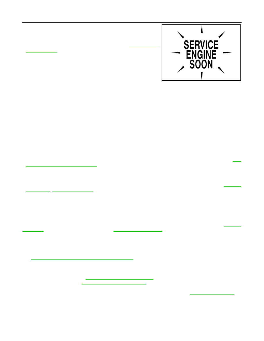
The ECM has an on board diagnostic system. It will light up the malfunction indicator lamp (MIL) to warn the
driver of a malfunction causing emission deterioration.
CAUTION:
• Be sure to turn the ignition switch OFF and disconnect the battery cable from the negative terminal
before any repair or inspection work. The open/short circuit of related switches, sensors, solenoid
valves, etc. will cause the MIL to light up.
• Be sure to connect and lock the connectors securely after work. A loose (unlocked) connector will
cause the MIL to light up due to an open circuit. (Be sure the connector is free from water, grease,
dirt, bent terminals, etc.)
• Be sure to route and secure the harnesses properly after work. Interference of the harness with a
bracket, etc. may cause the MIL to light up due to a short circuit.
• Be sure to connect rubber tubes properly after work. A misconnected or disconnected rubber tube
may cause the MIL to light up due to a malfunction of the EVAP system or fuel injection system, etc.
• Be sure to erase the unnecessary malfunction information (repairs completed) from the TCM and
ECM before returning the vehicle to the customer.
General Precautions
INFOID:0000000003130582
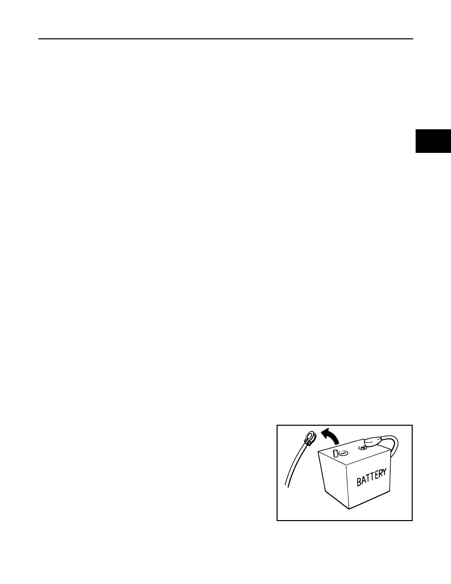
• Turn ignition switch OFF and disconnect the battery cable
from the negative terminal before connecting or disconnect-
ing the A/T assembly harness connector. Because battery
voltage is applied to TCM even if ignition switch is turned
OFF.
SEF289H
TM-138
< PRECAUTION >
[5AT: RE5R05A]
PRECAUTIONS
• Perform “DTC (Diagnostic Trouble Code) CONFIRMATION
PROCEDURE” after performing each TROUBLE DIAGNOSIS.
If the repair is completed DTC should not be displayed in the
“DTC CONFIRMATION PROCEDURE”.
• Always use the specified brand of ATF. Refer to
.
• Use lint-free paper not cloth rags during work.
• Dispose of the waste oil using the methods prescribed by law, ordi-
nance, etc. after replacing the ATF.
• Before proceeding with disassembly, thoroughly clean the outside
of the transmission. It is important to prevent the internal parts from
becoming contaminated by dirt or other foreign matter.
• Disassembly should be done in a clean work area.
• Use lint-free paper or towels for wiping parts clean. Common shop rags can leave fibers that could interfere
with the operation of the transmission.
• Place disassembled parts in order for easier and proper assembly.
• All parts should be carefully cleaned with a general purpose, non-flammable solvent before inspection or
reassembly.
• Gaskets, seals and O-rings should be replaced any time the A/T is disassembled.
• It is very important to perform functional tests whenever they are indicated.
• The valve body contains precision parts and requires extreme care when parts are removed and serviced.
Place disassembled valve body parts in order for easier and proper assembly. Care will also prevent springs
and small parts from becoming scattered or lost.
• Properly installed valves, sleeves, plugs, etc. will slide along bores in valve body under their own weight.
• Before assembly, apply a coat of recommended ATF to all parts. Apply petroleum jelly to protect O-rings and
seals, or hold bearings and washers in place during assembly. Do not use grease.
• Extreme care should be taken to avoid damage to O-rings, seals and gaskets when assembling.
• Clean or replace ATF cooler if excessive foreign material is found in oil pan or clogging strainer. Refer to
138, "Service Notice or Precaution"
• Refill the transmission with new ATF after overhaul.
• When the A/T drain plug is removed, only some of the ATF is drained. Old ATF will remain in torque con-
verter and ATF cooling system.
Always follow the procedures under “Inspection” and “Changing” when changing ATF. Refer to
Service Notice or Precaution
INFOID:0000000003130583
ATF COOLER SERVICE
If ATF contains frictional material (clutches, bands, etc.), or if an A/T is repaired, overhauled, or replaced,
inspect and clean the A/T fluid cooler mounted in the radiator or replace the radiator. Flush cooler lines using
cleaning solvent and compressed air after repair. For A/T fluid cooler cleaning procedure, refer to
. For radiator replacement, refer to
.
OBD-II SELF-DIAGNOSIS
• A/T self-diagnosis is performed by the TCM in combination with the ECM. The results can be read through
the blinking pattern of the A/T CHECK indicator lamp or the malfunction indicator lamp (MIL). Refer to the
table on “SELF-DIAGNOSTIC RESULTS” for the indicator used to display each self-diagnostic result. Refer
to
TM-40, "CONSULT-III Function (TRANSMISSION)"
• The self-diagnostic results indicated by the MIL are automatically stored in both the ECM and TCM memo-
ries.
Always perform the procedure on “How to Erase DTC” to complete the repair and avoid unnecessary
blinking of the MIL. Refer to
TM-39, "Diagnosis Description"
For details of OBD-II, refer to
EC-100, "Diagnosis Description"
• Certain systems and components, especially those related to OBD, may use the new style slide-lock-
ing type harness connector. For description and how to disconnect, refer to
.
SEF217U

PREPARATION
TM-139
< PREPARATION >
[5AT: RE5R05A]
C
E
F
G
H
I
J
K
L
M
A
B
TM
N
O
P
PREPARATION
PREPARATION
Special Service Tool
INFOID:0000000003130584
The actual shapes of Kent-Moore tools may differ from those of special service tools illustrated here.
Tool number
(Kent-Moore No.)
Tool name
Description
ST2505S001
(J-34301-C)
Oil pressure gauge set
1. ST25051001
(
—
)
Oil pressure gauge
2. ST25052000
(
—
)
Hose
3. ST25053000
(
—
)
Joint pipe
4. ST25054000
(
—
)
Adapter
5. ST25055000
(
—
)
Adapter
Measuring line pressure
KV31103600
(J-45674)
Joint pipe adapter
(With ST25054000)
Measuring line pressure
ST33400001
(J-26082)
Drift
a: 60 mm (2.36 in) dia.
b: 47 mm (1.85 in) dia.
• Installing rear oil seal (2WD)
• Installing oil pump housing oil seal
KV31102400
(J-34285 and J-34285-87)
Clutch spring compressor
a: 320 mm (12.60 in)
b: 174 mm (6.85 in)
Installing reverse brake return spring retainer
ST25850000
(J-25721-A)
Sliding hammer
a: 179 mm (7.05 in)
b: 70 mm (2.76 in)
c: 40 mm (1.57 in)
d: M12X1.75P
Remove oil pump assembly
SCIA3695J
ZZA1227D
NT086
NT423
NT422
Нет комментариевНе стесняйтесь поделиться с нами вашим ценным мнением.
Текст