Infiniti EX35. Manual — part 845
FAX-10
< PRECAUTION >
[AWD]
PRECAUTIONS
PRECAUTION
PRECAUTIONS
Precaution for Supplemental Restraint System (SRS) "AIR BAG" and "SEAT BELT
PRE-TENSIONER"
INFOID:0000000003138930
The Supplemental Restraint System such as “AIR BAG” and “SEAT BELT PRE-TENSIONER”, used along
with a front seat belt, helps to reduce the risk or severity of injury to the driver and front passenger for certain
types of collision. This system includes seat belt switch inputs and dual stage front air bag modules. The SRS
system uses the seat belt switches to determine the front air bag deployment, and may only deploy one front
air bag, depending on the severity of a collision and whether the front occupants are belted or unbelted.
Information necessary to service the system safely is included in the “SRS AIRBAG” and “SEAT BELT” of this
Service Manual.
WARNING:
• To avoid rendering the SRS inoperative, which could increase the risk of personal injury or death in
the event of a collision which would result in air bag inflation, all maintenance must be performed by
an authorized NISSAN/INFINITI dealer.
• Improper maintenance, including incorrect removal and installation of the SRS, can lead to personal
injury caused by unintentional activation of the system. For removal of Spiral Cable and Air Bag
Module, see the “SRS AIRBAG”.
• Do not use electrical test equipment on any circuit related to the SRS unless instructed to in this
Service Manual. SRS wiring harnesses can be identified by yellow and/or orange harnesses or har-
ness connectors.
Precaution Necessary for Steering Wheel Rotation after Battery Disconnect
INFOID:0000000003138931
NOTE:
• Before removing and installing any control units, first turn the push-button ignition switch to the LOCK posi-
tion, then disconnect both battery cables.
• After finishing work, confirm that all control unit connectors are connected properly, then re-connect both
battery cables.
• Always use CONSULT-III to perform self-diagnosis as a part of each function inspection after finishing work.
If a DTC is detected, perform trouble diagnosis according to self-diagnosis results.
This vehicle is equipped with a push-button ignition switch and a steering lock unit.
If the battery is disconnected or discharged, the steering wheel will lock and cannot be turned.
If turning the steering wheel is required with the battery disconnected or discharged, follow the procedure
below before starting the repair operation.
OPERATION PROCEDURE
1.
Connect both battery cables.
NOTE:
Supply power using jumper cables if battery is discharged.
2.
Carry the Intelligent Key or insert it to the key slot and turn the push-button ignition switch to ACC position.
(At this time, the steering lock will be released.)
3.
Disconnect both battery cables. The steering lock will remain released with both battery cables discon-
nected and the steering wheel can be turned.
4.
Perform the necessary repair operation.
5.
When the repair work is completed, re-connect both battery cables. With the brake pedal released, turn
the push-button ignition switch from ACC position to ON position, then to LOCK position. (The steering
wheel will lock when the push-button ignition switch is turned to LOCK position.)
6.
Perform self-diagnosis check of all control units using CONSULT-III.
Precautions for Drive Shaft
INFOID:0000000003138933
CAUTION:
Observe the following precautions when disassembling and assembling drive shaft.
• Joint sub-assembly does not disassemble because it is non-overhaul parts.
• Perform work in a location which is as dust-free as possible.
PRECAUTIONS
FAX-11
< PRECAUTION >
[AWD]
C
E
F
G
H
I
J
K
L
M
A
B
FAX
N
O
P
• Before disassembling and assembling, clean the outside of parts.
• Prevention of the entry of foreign objects must be taken into account during disassembly of the ser-
vice location.
• Disassembled parts must be carefully reassembled in the correct order. If work is interrupted, a
clean cover must be placed over parts.
• Paper waste must be used. Fabric shop cloths must not be used because of the danger of lint adher-
ing to parts.
• Disassembled parts (except for rubber parts) should be cleaned with kerosene which shall be
removed by blowing with air or wiping with paper waste.
FAX-12
< PREPARATION >
[AWD]
PREPARATION
PREPARATION
PREPARATION
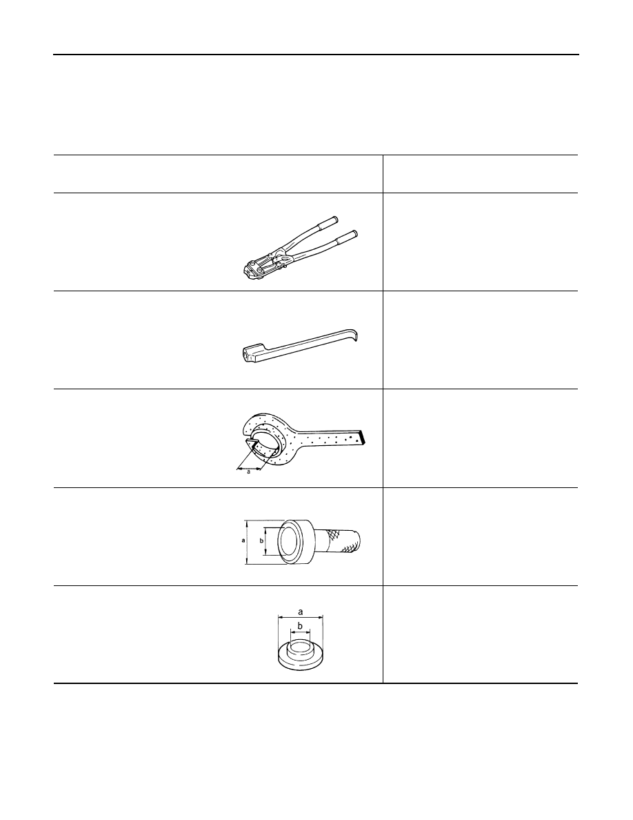
Special Service Tool
INFOID:0000000003138934
The actual shapes of Kent-Moore tools may differ from those of special service tools illustrated here.
Tool number
(Kent-Moore No.)
Tool name
Description
KV40107300
(
−
)
Boot band crimping tool
Installing boot band
KV40107500
(
−
)
Drive shaft attachment
Removing drive shaft
KV38107900
(
−
)
Protector
a: 32 mm (1.26 in) dia.
Installing drive shaft
KV38100500
(
−
)
Drift
a: 80 mm (3.15 in) dia.
b: 60 mm (2.36 in) dia.
Installing drive shaft plug
KV38102200
(
−
)
Drift
a: 90 mm (3.54 in) dia.
b: 31 mm (1.22 in) dia.
Installing drive shaft plug
ZZA1229D
ZZA1230D
PDIA1183J
ZZA0701D
ZZA0920D

PREPARATION
FAX-13
< PREPARATION >
[AWD]
C
E
F
G
H
I
J
K
L
M
A
B
FAX
N
O
P
Commercial Service Tool
INFOID:0000000003138935
Tool name
Description
Power tool
Loosening bolts and nuts
PBIC0190E
Нет комментариевНе стесняйтесь поделиться с нами вашим ценным мнением.
Текст