Infiniti EX35. Manual — part 797
EXL-232
< FUNCTION DIAGNOSIS >
[HALOGEN TYPE]
DIAGNOSIS SYSTEM (BCM)
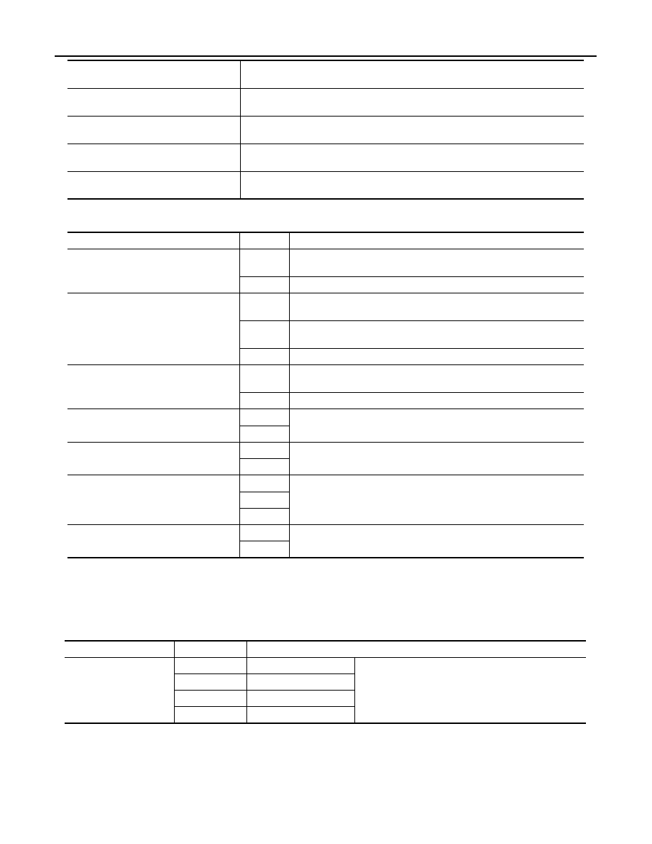
ACTIVE TEST
FLASHER
FLASHER : CONSULT-III Function (BCM - FLASHER)
INFOID:0000000003757049
WORK SUPPORT
*: Initial setting
DATA MONITOR
DOOR SW-RR
[On/Off]
The switch status input from rear door switch RH
DOOR SW- RL
[On/Off]
The switch status input from rear door switch LH
DOOR SW-BK
[On/Off]
NOTE:
The item is indicated, but not monitored.
OPTICAL SENSOR
[V]
The value of exterior brightness voltage input from the optical sensor
Monitor item
[Unit]
Description
Test item
Operation
Description
TAIL LAMP
On
Transmits the position light request signal to IPDM E/R with CAN com-
munication to turn the tail lamp ON.
Off
Stops the position light request signal transmission.
HEAD LAMP
Hi
Transmits the high beam request signal with CAN communication to turn
the headlamp (HI).
Low
Transmits the low beam request signal with CAN communication to turn
the headlamp (LO).
Off
Stops the high & low beam request signal transmission.
FR FOG LAMP
On
Transmits the front fog light request signal to IPDM E/R with CAN com-
munication to turn the front fog lamp ON.
Off
Stops the front fog light request signal transmission.
RR FOG LAMP
On
NOTE:
The item is indicated, but cannot be tested.
Off
DAYTIME RUNNING LIGHT
On
NOTE:
The item is indicated, but cannot be tested.
Off
CORNERING LAMP
RH
NOTE:
The item is indicated, but cannot be tested.
LH
Off
ILL DIM SIGNAL
On
NOTE:
The item is indicated, but cannot be tested.
Off
Service item
Setting item
Setting
HAZARD ANSWER
BACK
Lock Only*
With locking only
Sets the hazard warning lamp answer back function
when the door is lock/unlock with the request switch or
the key fob.
Unlk Only
With unlocking only
Lock/Unlk
With locking/unlocking
Off
Without the function

DIAGNOSIS SYSTEM (BCM)
EXL-233
< FUNCTION DIAGNOSIS >
[HALOGEN TYPE]
C
D
E
F
G
H
I
J
K
M
A
B
EXL
N
O
P
ACTIVE TEST
Monitor item
[Unit]
Description
REQ SW-DR
[On/Off]
The switch status input from the request switch (driver side)
REQ SW-AS
[On/Off]
The switch status input from the request switch (passenger side)
PUSH SW
[On/Off]
The switch status input from the push-button ignition switch
TURN SIGNAL R
[On/Off]
Each switch condition that BCM judges from the combination switch reading function
TURN SIGNAL L
[On/Off]
HAZARD SW
[On/Off]
The switch status input from the hazard switch
RKE-LOCK
[On/Off]
Lock signal status received from the remote keyless entry receiver
RKE-UNLOCK
[On/Off]
Unlock signal status received from the remote keyless entry receiver
RKE-PANIC
[On/Off]
Panic alarm signal status received from the remote keyless entry receiver
Test item
Operation
Description
FLASHER
RH
Outputs the voltage to blink the right side turn signal lamps.
LH
Outputs the voltage to blink the left side turn signal lamps.
Off
Stops the voltage to turn the turn signal lamps OFF.
EXL-234
< FUNCTION DIAGNOSIS >
[HALOGEN TYPE]
DIAGNOSIS SYSTEM (IPDM E/R)
DIAGNOSIS SYSTEM (IPDM E/R)
Diagnosis Description
INFOID:0000000003757052
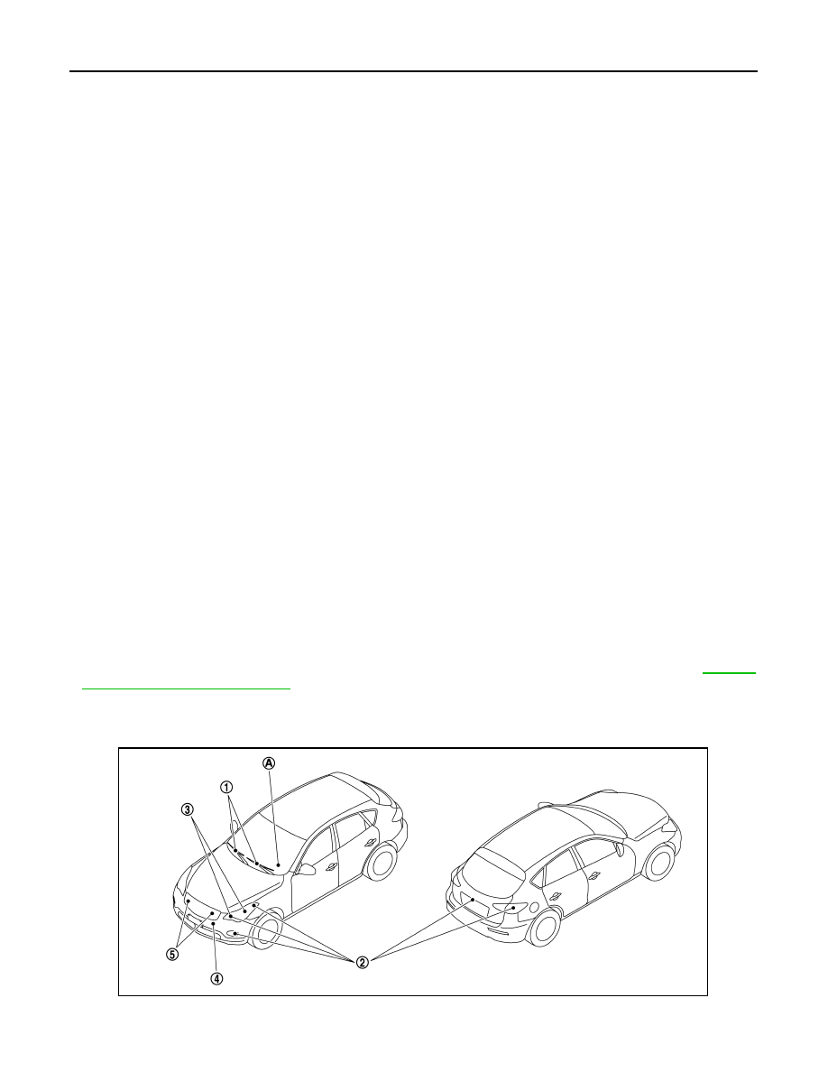
AUTO ACTIVE TEST
Description
In auto active test mode, the IPDM E/R sends a drive signal to the following systems to check their operation.
• Oil pressure warning lamp
• Front wiper (LO, HI)
• Parking lamps
• License plate lamps
• Side maker lamps
• Tail lamps
• Front fog lamps
• Headlamps (LO, HI)
• A/C compressor (magnet clutch)
• Cooling fan (cooling fan control module)
Operation Procedure
1.
Close the hood and lift the wiper arms from the windshield. (Prevent windshield damage due to wiper
operation)
NOTE:
When auto active test is performed with hood opened, sprinkle water on windshield beforehand.
2.
Turn ignition switch OFF.
3.
Turn the ignition switch ON, and within 20 seconds, press the driver door switch 10 times. Then turn the
ignition switch OFF.
CAUTION:
Close passenger door.
4.
Turn the ignition switch ON within 10 seconds. After that the horn sounds once and the auto active test
starts.
5.
The oil pressure warning lamp starts blinking when the auto active test starts.
6.
After a series of the following operations is repeated 3 times, auto active test is completed.
NOTE:
When auto active test mode has to be cancelled halfway through test, turn ignition switch OFF.
CAUTION:
• If auto active test mode cannot be actuated, check door switch system. Refer to
.
• Do not start the engine.
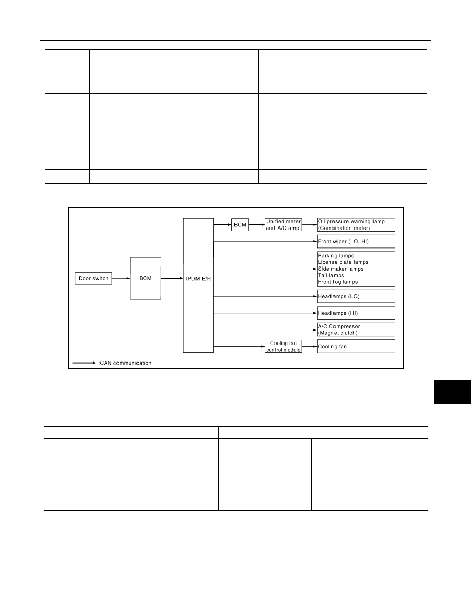
Inspection in Auto Active Test Mode
When auto active test mode is actuated, the following 5 steps are repeated 3 times.
JPMIA0950ZZ
DIAGNOSIS SYSTEM (IPDM E/R)
EXL-235
< FUNCTION DIAGNOSIS >
[HALOGEN TYPE]
C
D
E
F
G
H
I
J
K
M
A
B
EXL
N
O
P
*: Outputs duty ratio of 50% for 5 seconds
→
duty ratio of 100% for 5 seconds on the cooling fan control module.
Concept of auto active test
• IPDM E/R starts the auto active test with the door switch signals transmitted by BCM via CAN communica-
tion. Therefore, the CAN communication line between IPDM E/R and BCM is considered normal if the auto
active test starts successfully.
• The auto active test facilitates troubleshooting if any systems controlled by IPDM E/R cannot be operated.
Diagnosis chart in auto active test mode
Operation
sequence
Inspection location
Operation
A
Oil pressure warning lamp
Blinks continuously during operation of auto active test
1
Front wiper
LO for 5 seconds
→
HI for 5 seconds
2
• Parking lamps
• License plate lamps
• Side maker lamps
• Tail lamps
• Front fog lamps
10 seconds
3
Headlamps
• LO 10 seconds
• HI ON
⇔
OFF 5 times
4
A/C compressor (magnet clutch)
ON
⇔
OFF 5 times
5
*
Cooling fan
MID for 5 seconds
→
HI for 5 seconds
JPMIA0009GB
Symptom
Inspection contents
Possible cause
Any of the following components do not operate
• Parking lamps
• License plate lamps
• Side maker lamps
• Tail lamps
• Front fog lamps
• Headlamp (HI, LO)
• Front wiper
Perform auto active test.
Does the applicable system
operate?
YES
BCM signal input circuit
NO
• Lamp or motor
• Lamp or motor ground cir-
cuit
• Harness or connector be-
tween IPDM E/R and appli-
cable system
• IPDM E/R
Нет комментариевНе стесняйтесь поделиться с нами вашим ценным мнением.
Текст