Infiniti EX35. Manual — part 1120

MWI-158
< SYMPTOM DIAGNOSIS >
THE DOOR OPEN WARNING CONTINUES DISPLAYING, OR DOES NOT DIS-
PLAY
THE DOOR OPEN WARNING CONTINUES DISPLAYING, OR DOES NOT
DISPLAY
Description
INFOID:0000000003140258
• The door ajar warning is displayed even though all of the doors are closed.
• The door ajar warning is not displayed even though a door is ajar.
Diagnosis Procedure
INFOID:0000000003140259
1.
CHECK BCM INPUT/OUTPUT SIGNAL
Connect CONSULT-III and check the BCM input signals. Refer to
DLK-63, "Component Function Check"
Is the inspection result normal?
YES
>> GO TO 2.
NO
>> GO TO 3.
2.
CHECK UNIFIED METER AND A/C AMP. INPUT SIGNAL
Select the “Data Monitor” for the “METER/M&A” and check the “DOOR W/L” monitor value.
Is the inspection result normal?
YES
>> Replace combination meter.
NO
>> Replace BCM. Refer to
BCS-84, "Removal and Installation"
3.
CHECK DOOR SWITCH SIGNAL CIRCUIT
Check the door switch signal circuit. Refer to
.
Is the inspection result normal?
YES
>> GO TO 4.
NO
>> Repair harness or connector.
4.
CHECK DOOR SWITCH UNIT
Perform a unit check for the door switch. Refer to
DLK-65, "Component Inspection"
.
Is the inspection result normal?
YES
>> Replace combination meter.
NO
>> Replace applicable door switch. Refer to
DLK-257, "Removal and Installation"
.
“DOOR W/L”
Door open
: On
Door closed
: Off

MWI
THE AMBIENT TEMPERATURE DISPLAY IS INCORRECT
MWI-159
< SYMPTOM DIAGNOSIS >
C
D
E
F
G
H
I
J
K
L
M
B
A
O
P
THE AMBIENT TEMPERATURE DISPLAY IS INCORRECT
Description
INFOID:0000000003140262
• The displayed ambient air temperature is higher than the actual temperature.
• The displayed ambient air temperature is lower than the actual temperature.
Diagnosis Procedure
INFOID:0000000003140263
NOTE:
Check that the symptom is not applicable to the normal operating condition before starting diagnosis. Refer to
MWI-160, "INFORMATION DISPLAY : Description"
1.
CHECK AMBIENT SENSOR SIGNAL CIRCUIT
Check the ambient sensor signal circuit. Refer to
Is the inspection result normal?
YES
>> GO TO 2.
NO
>> Repair harness or connector.
2.
CHECK AMBIENT SENSOR UNIT
Perform a unit check for the ambient sensor. Refer to
HAC-92, "Component Inspection"
Is the inspection result normal?
YES
>> Replace unified meter and A/C amp.
NO
>> Replace ambient sensor. Refer to
MWI-160
< SYMPTOM DIAGNOSIS >
NORMAL OPERATING CONDITION
NORMAL OPERATING CONDITION
COMPASS
COMPASS : Description
INFOID:0000000003140264
COMPASS
• The electronic compass is highly protected from changes in most magnetic fields. However, some large
changes in magnetic fields can affect it. Some examples are (but not limited to): high tension power lines,
large steel buildings, subways, steel bridges, automatic car washes, large piles of scrap metal, etc. While
this does not happen very often, it is possible.
• During normal operation, the Compass Mirror will continuously update the compass calibration to adjust for
gradual changes in the vehicle's magnetic “remnant” field. If the vehicle is subjected to high magnetic influ-
ences, the compass may appear to indicate false headings, become locked, or appear that it is unable to be
calibrated. If this occurs, perform the calibration procedure.
• If at any time the compass continually displays the incorrect direction or the reading is erratic or locked, ver-
ify the correct zone variance.
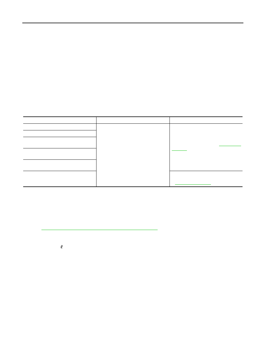
Symptom Chart
INFORMATION DISPLAY
INFORMATION DISPLAY : Description
INFOID:0000000003140265
AMBIENT AIR TEMPERATURE
The displayed ambient air temperature on the information display may differ from the actual temperature
because it is a corrected value calculated from the ambient sensor signal by the unified meter and A/C amp.
Refer to
MWI-29, "INFORMATION DISPLAY : System Description"
for details on the correction process.
POSSIBLE DRIVING DISTANCE
The calculated possible driving distance may differ from the actual distance to empty if the refueling amount is
approximately 15 (4 US gal, 3-3/10 Imp gal) or less. This is because the refuel control (moves the fuel
gauge needle quicker than normal judging that the driver is refueling the vehicle) is not performed in such a
case.
Symptom
Cause
Solution / Reference
The compass display reads “C”.
• Compass is not calibrated.
• Incorrect zone variance setting.
• Large change in magnetic field (Steel
bridges, subways, concentrations of
metal, carwashes, etc.)
• Compass was calibrated incorrectly or in
the presence of a strong magnetic field.
Perform calibration. Refer to
.
Compass shows the wrong direction.
Compass does not change direction ap-
pears “Locked”.
Compass does not show all the directions,
one or more is missing.
The compass was calibrated but it “loses”
calibration.
On long trips the compass shows the
wrong direction.
Perform zone variation setting if correct
reading is desired in that location. Refer
to
.
MWI
PRECAUTIONS
MWI-161
< PRECAUTION >
C
D
E
F
G
H
I
J
K
L
M
B
A
O
P
PRECAUTION
PRECAUTIONS
Precaution for Supplemental Restraint System (SRS) "AIR BAG" and "SEAT BELT
PRE-TENSIONER"
INFOID:0000000003733150
The Supplemental Restraint System such as “AIR BAG” and “SEAT BELT PRE-TENSIONER”, used along
with a front seat belt, helps to reduce the risk or severity of injury to the driver and front passenger for certain
types of collision. This system includes seat belt switch inputs and dual stage front air bag modules. The SRS
system uses the seat belt switches to determine the front air bag deployment, and may only deploy one front
air bag, depending on the severity of a collision and whether the front occupants are belted or unbelted.
Information necessary to service the system safely is included in the “SRS AIRBAG” and “SEAT BELT” of this
Service Manual.
WARNING:
• To avoid rendering the SRS inoperative, which could increase the risk of personal injury or death in
the event of a collision which would result in air bag inflation, all maintenance must be performed by
an authorized NISSAN/INFINITI dealer.
• Improper maintenance, including incorrect removal and installation of the SRS, can lead to personal
injury caused by unintentional activation of the system. For removal of Spiral Cable and Air Bag
Module, see the “SRS AIRBAG”.
• Do not use electrical test equipment on any circuit related to the SRS unless instructed to in this
Service Manual. SRS wiring harnesses can be identified by yellow and/or orange harnesses or har-
ness connectors.
Нет комментариевНе стесняйтесь поделиться с нами вашим ценным мнением.
Текст