Infiniti EX35. Manual — part 1549
WW-48
< ECU DIAGNOSIS >
BCM (BODY CONTROL MODULE)
CONFIRM ID1
The key ID that the key slot receives does not accord with the first
key ID registered to BCM.
Yet
The key ID that the key slot receives accords with the first key ID
registered to BCM.
DONE
TP 4
The ID of fourth key is not registered to BCM
Yet
The ID of fourth key is registered to BCM
DONE
TP 3
The ID of third key is not registered to BCM
Yet
The ID of third key is registered to BCM
DONE
TP 2
The ID of second key is not registered to BCM
Yet
The ID of second key is registered to BCM
DONE
TP 1
The ID of first key is not registered to BCM
Yet
The ID of first key is registered to BCM
DONE
AIR PRESS FL
Ignition switch ON (Only when the signal from the transmitter is re-
ceived)
Air pressure of front LH tire
AIR PRESS FR
Ignition switch ON (Only when the signal from the transmitter is re-
ceived)
Air pressure of front RH tire
AIR PRESS RR
Ignition switch ON (Only when the signal from the transmitter is re-
ceived)
Air pressure of rear RH tire
AIR PRESS RL
Ignition switch ON (Only when the signal from the transmitter is re-
ceived)
Air pressure of rear LH tire
ID REGST FL1
ID of front LH tire transmitter is registered
DONE
ID of front LH tire transmitter is not registered
Yet
ID REGST FR1
ID of front RH tire transmitter is registered
DONE
ID of front RH tire transmitter is not registered
Yet
ID REGST RR1
ID of rear RH tire transmitter is registered
DONE
ID of rear RH tire transmitter is not registered
Yet
ID REGST RL1
ID of rear LH tire transmitter is registered
DONE
ID of rear LH tire transmitter is not registered
Yet
WARNING LAMP
Tire pressure indicator OFF
Off
Tire pressure indicator ON
On
BUZZER
Tire pressure warning alarm is not sounding
Off
Tire pressure warning alarm is sounding
On
Monitor Item
Condition
Value/Status
BCM (BODY CONTROL MODULE)
WW-49
< ECU DIAGNOSIS >
C
D
E
F
G
H
I
J
K
M
A
B
WW
N
O
P
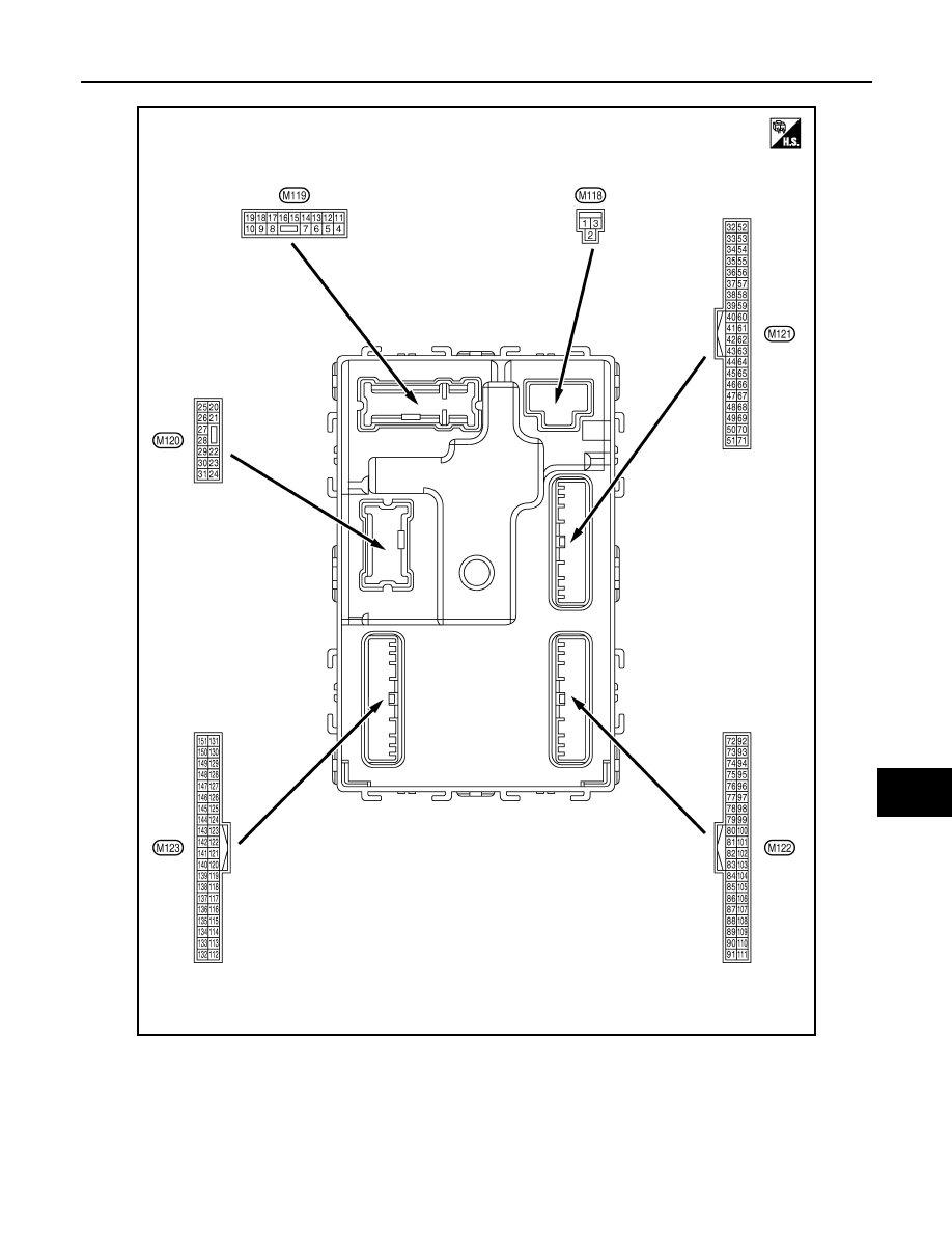
TERMINAL LAYOUT
PHYSICAL VALUES
JPMIA0062ZZ
WW-50
< ECU DIAGNOSIS >
BCM (BODY CONTROL MODULE)
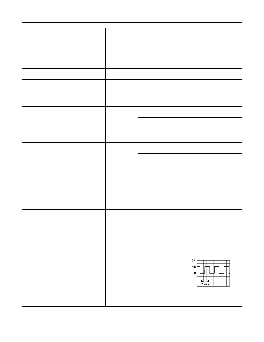
Terminal No.
(Wire color)
Description
Condition
Value
(Approx.)
Signal name
Input/
Output
+
–
1
(W)
Ground
Battery power supply
Input
Ignition switch OFF
Battery voltage
2
(Y)
Ground
P/W power supply
(BAT)
Output
Ignition switch OFF
Battery voltage
3
(O)
Ground
P/W power supply
(RAP)
Output
Ignition switch ON
Battery voltage
4
(LG)
Ground
Interior room lamp
power supply
Output
Interior room lamp battery saver is activated.
(Cuts the interior room lamp power supply)
0 V
Interior room lamp battery saver is not activat-
ed.
(Outputs the interior room lamp power supply)
Battery voltage
5
(L)
Ground
Passenger door UN-
LOCK
Output
Passenger door
UNLOCK
(Actuator is activated)
Battery voltage
Other than UNLOCK
(Actuator is not activated)
0 V
7
(Y)
Ground
Step lamp
Output
Step lamp
ON
0 V
OFF
Battery voltage
8
(V)
Ground
All doors, fuel lid
LOCK
Output
All doors
LOCK
(Actuator is activated)
Battery voltage
Other than LOCK
(Actuator is not activated)
0 V
9
(G)
Ground
Driver door, fuel lid
UNLOCK
Output
Driver door
UNLOCK
(Actuator is activated)
Battery voltage
Other than UNLOCK
(Actuator is not activated)
0 V
10
(BR)
Ground
Rear RH door and
rear LH door UN-
LOCK
Output
Rear RH door
and rear LH door
UNLOCK
(Actuator is activated)
Battery voltage
Other than UNLOCK
(Actuator is not activated)
0 V
11
(R)
Ground
Battery power supply
Input
Ignition switch OFF
Battery voltage
13
(B)
Ground
Ground
—
Ignition switch ON
0 V
14
(W)
Ground
Push-button ignition
switch illumination
ground
Output
Tail lamp
OFF
0 V
ON
NOTE:
When the illumination brighten-
ing/dimming level is in the neutral
position
15
(Y)
Ground
ACC indicator lamp
Output
Ignition switch
OFF or ON
Battery voltage
ACC
0 V
JSNIA0010GB
BCM (BODY CONTROL MODULE)
WW-51
< ECU DIAGNOSIS >
C
D
E
F
G
H
I
J
K
M
A
B
WW
N
O
P
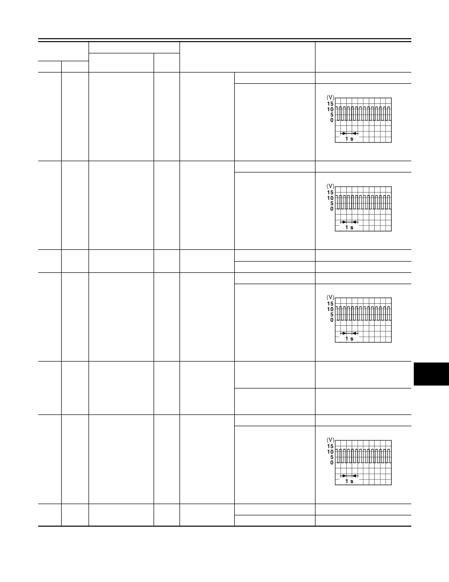
17
(W)
Ground
Turn signal RH
(Front)
Output
Ignition switch
ON
Turn signal switch OFF
0 V
Turn signal switch RH
6.5 V
18
(O)
Ground
Turn signal LH
(Front)
Output
Ignition switch
ON
Turn signal switch OFF
0 V
Turn signal switch LH
6.5 V
19
(V)
Ground
Room lamp timer
control
Output
Interior room
lamp
OFF
Battery voltage
ON
0 V
20
(V)
Ground
Turn signal RH
(Rear)
Output
Ignition switch
ON
Turn signal switch OFF
0 V
Turn signal switch RH
6.5 V
23
(G)
Ground
Back door opening
Output
Back door
OPEN
(Back door opener actuator
is activated)
Battery voltage
Other than OPEN
(Back door opener actuator
is not activated)
0 V
25
(G)
Ground
Turn signal LH (Rear)
Output
Ignition switch
ON
Turn signal switch OFF
0 V
Turn signal switch LH
6.5 V
26
(G)
Ground
Rear wiper
Output
Rear wiper
OFF (Stopped)
0 V
ON (Operated)
Battery voltage
Terminal No.
(Wire color)
Description
Condition
Value
(Approx.)
Signal name
Input/
Output
+
–
PKID0926E
PKID0926E
PKID0926E
PKID0926E
Нет комментариевНе стесняйтесь поделиться с нами вашим ценным мнением.
Текст