Infiniti EX35. Manual — part 730
CYLINDER BLOCK
EM-119
< DISASSEMBLY AND ASSEMBLY >
C
D
E
F
G
H
I
J
K
L
M
A
EM
N
P
O
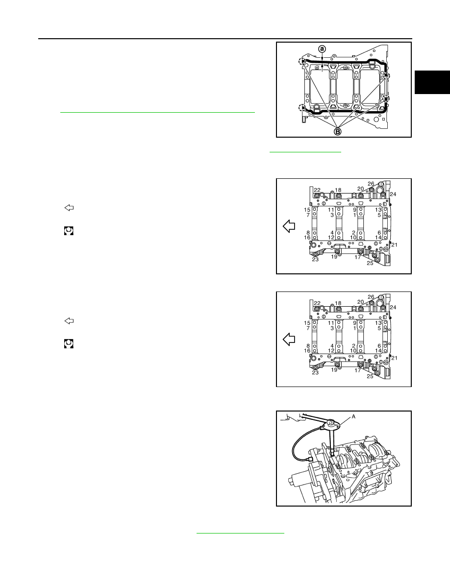
• Apply a continuous bead of liquid gasket with the tube presser
(commercial service tool) to lower cylinder block as shown in
the figure.
Use Genuine RTV Silicone Sealant or equivalent. Refer to
GI-15, "Recommended Chemical Products and Sealants"
7.
Inspect the outer diameter of lower cylinder block bolt. Refer to
.
8.
Install lower cylinder block bolts in numerical order as shown in the figure as follows:
a.
Apply new engine oil to threads and seat surfaces of lower cylinder block bolts.
b.
Tighten lower cylinder block bolts (No. 17 to 26) in numerical
order as shown in the figure.
c.
Repeat step b.
d.
Tighten lower cylinder block bolt (No. 1 to 16) in numerical order
as shown in the figure.
e.
Turn lower cylinder block bolt (No. 1 to 16) 90 degrees clockwise (angle tightening).
CAUTION:
Use the angle wrench [SST: KV10112100 (BT8653-A)] (A) to
check tightening angle. Never make judgment by visual
inspection.
• After installing lower cylinder block bolts, check that crankshaft can be rotated smoothly by hand.
• Check the crankshaft end play. Refer to
.
9.
Install piston to connecting rod as follows:
a.
Using a snap ring pliers, install new snap ring to the groove of piston rear side.
B
: Apply to end
a
:
φ
4.0 - 5.0 mm (0.157 - 0.197 in)
JPBIA1354ZZ
: Engine front
: 25.0 N·m (2.6 kg-m, 18 ft-lb)
JPBIA0197ZZ
: Engine front
: 35.3 N·m (3.6 kg-m, 26 ft-lb)
JPBIA0197ZZ
JPBIA0202ZZ
EM-120
< DISASSEMBLY AND ASSEMBLY >
CYLINDER BLOCK
• Insert it fully into groove to install.
b.
Install piston to connecting rod.
• Using an industrial use drier or similar tool, heat piston until piston pin can be pushed in by hand without
excess force [approximately 60 to 70
°
C (140 to 158
°
F)]. From the front to the rear, insert piston pin into
piston and connecting rod.
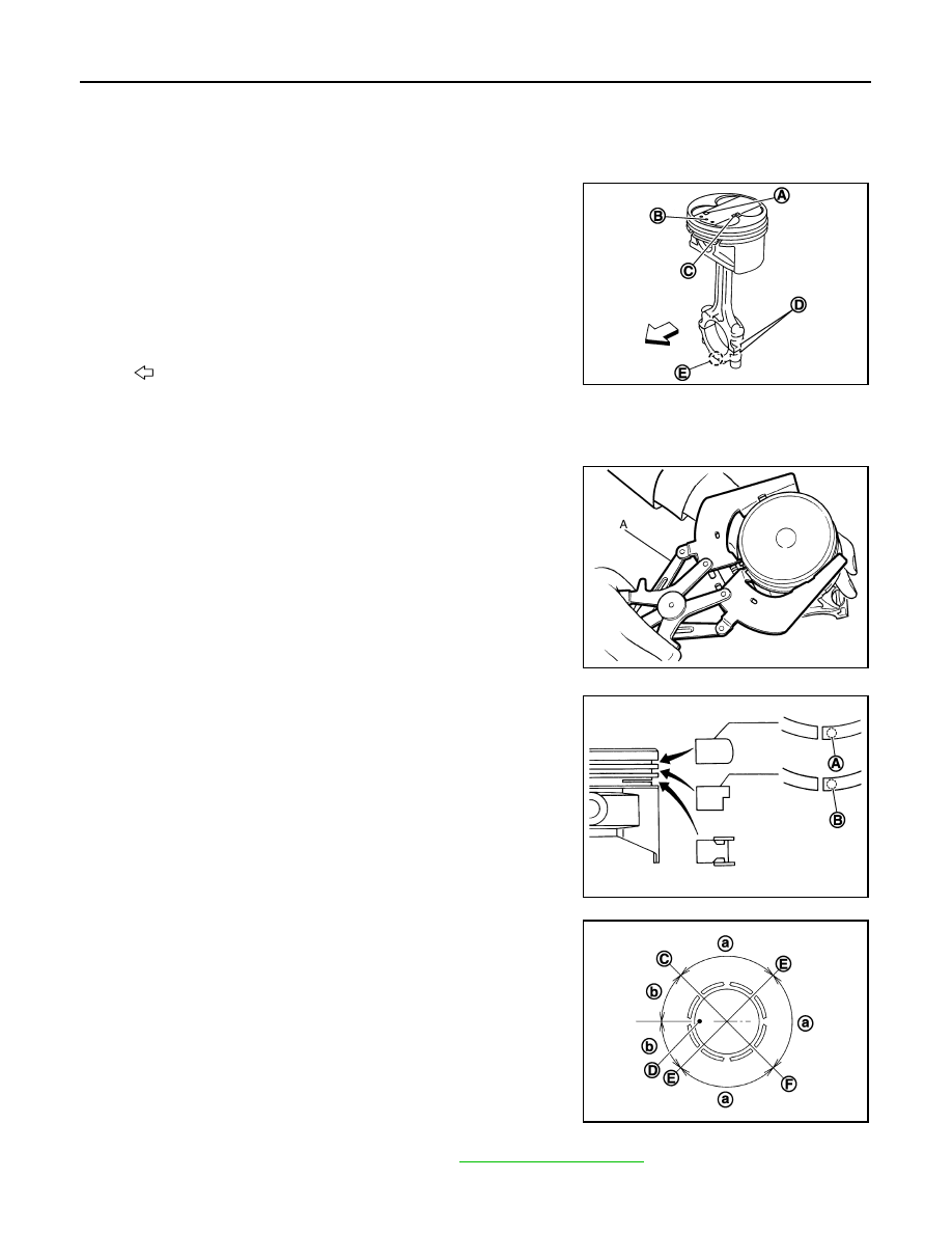
• Assemble so that the front mark on the piston head and the
cylinder number on connecting rod are positioned as shown in
the figure.
c.
Install new snap ring to the groove of the piston front side.
• Insert it fully into groove to install.
• After installing, check that connecting rod moves smoothly.
10. Using a piston ring expander (commercial service tool) (A),
install piston rings.
CAUTION:
• When installing piston rings, be careful not to damage
piston.
• Be careful not to damage piston rings by expending them
excessively.
• If there is stamped mark on ring, mount it with marked side up.
• Position each ring with the gap as shown in the figure referring
to the piston front mark (D).
• Check the piston ring side clearance. Refer to
.
11. Install connecting rod bearings to connecting rod and connecting rod bearing cap.
A
: Piston grade number
B
: Front mark
C
: Pin grade number
D
: Cylinder number
E
: Front mark
: Engine front
JPBIA0203ZZ
JPBIA0194ZZ
Stamped mark:
Top ring (A)
: 1 N
Second ring (B)
: 2 N
JPBIA0263ZZ
C
: Top ring gap
E
: Oil ring upper or lower rail gap (either of them)
F
: Second ring and oil ring spacer gap
a
: 90 degrees
b
: 45 degrees
JPBIA0205ZZ

CYLINDER BLOCK
EM-121
< DISASSEMBLY AND ASSEMBLY >
C
D
E
F
G
H
I
J
K
L
M
A
EM
N
P
O
CAUTION:
Be careful not to drop connecting rod bearing, and to scratch the surface.
• Before installing connecting rod bearings, apply engine oil to the bearing surface (inside). Do not apply
engine oil to the back surface, but thoroughly clean it.
• When installing, align connecting rod bearing stopper protru-
sion (B) with cutout (C) of connecting rods and connecting rod
bearing caps to install.
• Ensure the oil hole (A) on connecting rod and that on the cor-
responding bearing are aligned.
12. Install piston and connecting rod assembly to crankshaft.
• Position crankshaft pin corresponding to connecting rod to be installed onto the bottom dead center.
• Apply engine oil sufficiently to the cylinder bore, piston and crankshaft pin journal.
• Match the cylinder position with the cylinder number on connecting rod to install.
• Be sure that front mark on piston crown is facing front of engine.
• Using a piston ring compressor [SST: EM03470000 (J8037)]
(A) or suitable tool, install piston with the front mark on the pis-
ton crown facing the front of the engine.
CAUTION:
Be careful not to damage the cylinder wall and crankshaft
pin, resulting from an interference of the connecting rod big
end.
13. Install connecting rod bearing cap.
• Match the stamped cylinder number marks on connecting rod
with those on connecting rod bearing cap to install.
• Be sure that front mark (H) on connecting rod bearing cap is facing front of the engine.
14. Tighten connecting rod bolt as follows:
a.
Inspect the outer diameter of connecting rod bolt. Refer to
.
b.
Apply engine oil to the threads and seats of connecting rod bolts.
c.
Tighten connecting rod bolts.
d.
Completely loosen connecting rod bolts.
e.
Tighten connecting rod bolts.
JPBIA0206ZZ
JPBIA0207ZZ
A
: Sample codes
B
: Bearing stopper groove
C
: Small-end diameter grade
D
: Big-end diameter grade
E
: Weight grade
F
: Cylinder No.
G
: Management code
I
: Management code
: 28.4 N·m (2.9 kg-m, 21 ft-lb)
: 0 N·m (0 kg-m, 0 ft-lb)
JPBIA0208ZZ
EM-122
< DISASSEMBLY AND ASSEMBLY >
CYLINDER BLOCK
f.
Then turn connecting rod bolts 90 degrees clockwise (angle tightening).
CAUTION:
Always use the angle wrench [SST: KV10112100 (BT8653-
A)] (A). Never tightening based on visual check alone.
• After tightening connecting rod bolts, check that crankshaft
rotates smoothly.
• Check the connecting rod side clearance. Refer to
15. Install baffle plate.
16. Install new rear oil seal. Refer to
EM-77, "REAR OIL SEAL : Removal and Installation"
.
• Apply new engine oil to both oil seal lip and dust seal lip.
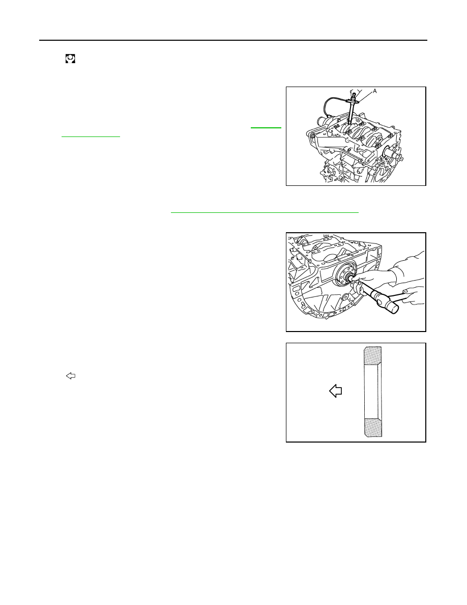
17. Install pilot converter.
• With a drift of the following outer diameter, press-fit as far as it
will go.
• Press-fit pilot converter with its chamfer facing crankshaft as
shown in the figure.
: 24.5 N·m (2.5 kg-m, 18 ft-lb)
JPBIA0209ZZ
Pilot converter
: Approximately 33 mm (1.30 in)
PBIC2947E
: Crankshaft side
JPBIA0210ZZ
Нет комментариевНе стесняйтесь поделиться с нами вашим ценным мнением.
Текст