Infiniti EX35. Manual — part 462
DLK-62
< COMPONENT DIAGNOSIS >
[INTELLIGENT KEY SYSTEM]
POWER SUPPLY AND GROUND CIRCUIT
POWER SUPPLY AND GROUND CIRCUIT
BCM (BODY CONTROL MODULE)
BCM (BODY CONTROL MODULE) : Diagnosis Procedure
INFOID:0000000003728860
1.
CHECK FUSE AND FUSIBLE LINK
Check that the following fuse and fusible link are not fusing.
Is the fuse fusing?
YES
>> Replace the blown fuse or fusible link after repairing the affected circuit if a fuse or fusible link is
blown.
NO
>> GO TO 2.
2.
CHECK POWER SUPPLY CIRCUIT
1.
Turn ignition switch OFF.
2.
Disconnect BCM connectors.
3.
Check voltage between BCM harness connector and ground.
Is the measurement value normal?
YES
>> GO TO 3.
NO
>> Repair or replace harness.
3.
CHECK GROUND CIRCUIT
Check continuity between BCM harness connector and ground.
Is the inspection result normal?
YES
>> INSPECTION END
NO
>> Repair or replace harness.
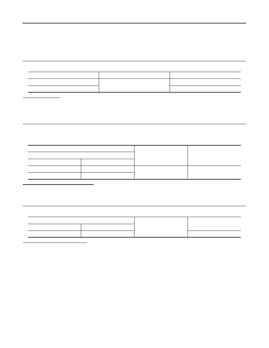
Terminal No.
Signal name
Fuse and fusible link No.
1
Battery power supply
K
11
10
(+)
(
−
)
Voltage
(Approx.)
BCM
Connector
Terminal
M118
1
Ground
Battery voltage
M119
11
BCM
Ground
Continuity
Connector
Terminal
M119
13
Existed
DOOR SWITCH
DLK-63
< COMPONENT DIAGNOSIS >
[INTELLIGENT KEY SYSTEM]
C
D
E
F
G
H
I
J
L
M
A
B
DLK
N
O
P
DOOR SWITCH
Description
INFOID:0000000003728862
Detects door open/close condition.
Component Function Check
INFOID:0000000003728863
1.
CHECK FUNCTION
With CONSULT-III
Check door switches (“DOOR SW-DR”, “DOOR SW-AS”, “DOOR SW-RL”, “DOOR SW-RR” and “DOOR SW-
BK”) in Data Monitor” mode with CONSULT-III.
Is the inspection result normal?
YES
>> Door switch is OK.
NO
>> Refer to
.
Diagnosis Procedure
INFOID:0000000003728864
1.
CHECK DOOR SWITCH INPUT SIGNAL
1.
Turn ignition switch OFF.
2.
Disconnect malfunctioning door switch connector.
3.
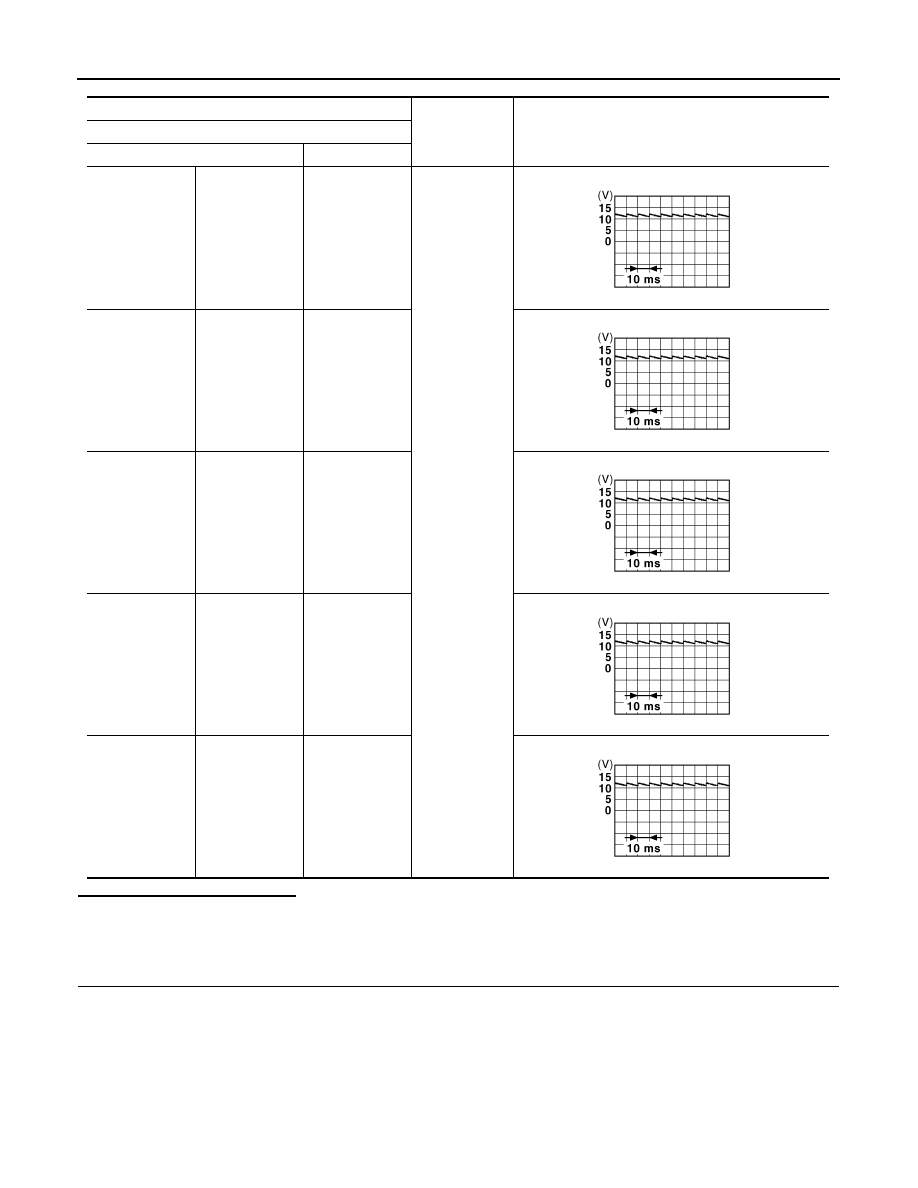
Check signal between malfunctioning door switch harness connector and ground with oscilloscope.
Monitor item
Condition
DOOR SW-DR
CLOSE
→
OPEN: OFF
→
ON
DOOR SW-AS
DOOR SW-RL
DOOR SW-RR
DOOR SW-BK
DLK-64
< COMPONENT DIAGNOSIS >
[INTELLIGENT KEY SYSTEM]
DOOR SWITCH
Is the inspection result normal?
YES-1 >> Back door: GO TO 3.
YES-2 >> Other doors: GO TO 4.
NO
>> GO TO 2.
2.
CHECK DOOR SWITCH CIRCUIT
1.
Disconnect BCM connector.
2.
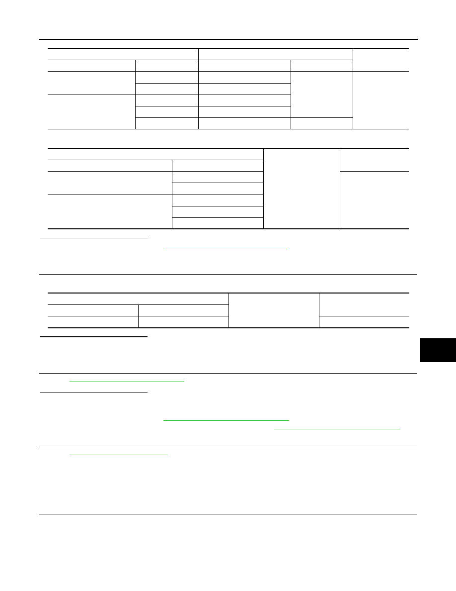
Check continuity between BCM harness connector and door switch harness connector.
(+)
(–)
Signal
(Reference value)
Door switch
Connector
Terminal
Driver side
B16
2
Ground
Passenger side
B216
2
Rear LH
B23
2
Rear RH
B223
2
Back door
D113
3
JPMIA0011GB
JPMIA0011GB
JPMIA0011GB
JPMIA0011GB
JPMIA0011GB
DOOR SWITCH
DLK-65
< COMPONENT DIAGNOSIS >
[INTELLIGENT KEY SYSTEM]
C
D
E
F
G
H
I
J
L
M
A
B
DLK
N
O
P
3.
Check continuity between BCM harness connector and ground.
Is the inspection result normal?
YES
>> Replace BCM. Refer to
BCS-84, "Removal and Installation"
NO
>> Repair or replace harness.
3.
CHECK BACK DOOR SWITCH GROUND CIRCUIT
Check continuity between back door lock assembly (back door switch) harness connector and ground.
Is the inspection result normal?
YES
>> GO TO 4.
NO
>> Repair or replace harness.
4.
CHECK DOOR SWITCH
DLK-65, "Component Inspection"
Is the inspection result normal?
YES
>> GO TO 5.
NO
>>
Replace malfunctioning door switch.
• Door switch: Refer to
DLK-257, "Removal and Installation"
.
• Back door lock assembly (back door switch): Refer to
DLK-255, "Removal and Installation"
5.
CHECK INTERMITTENT INCIDENT
GI-38, "Intermittent Incident"
.
>> INSPECTION END
Component Inspection
INFOID:0000000003728865
1.
CHECK DOOR SWITCH
1.
Turn ignition switch OFF.
2.
Disconnect door switch connector.
3.
Check door switch terminals.
BCM
Door switch
Continuity
Connector
Terminal
Connector
Terminal
M123
150
B16 (Driver side)
2
Existed
124
B216 (Passenger side)
M121
69
B23 (Rear LH)
68
B223 (Rear RH)
66
D113 (Back door)
3
BCM
Ground
Continuity
Connector
Terminal
M123
150 (Driver side)
Not existed
124 (Passenger side)
M121
69 (Rear LH)
68 (Rear RH)
66 (Back door)
Back door lock assembly (back door switch)
Ground
Continuity
Connector
Terminal
D113
4
Existed
Нет комментариевНе стесняйтесь поделиться с нами вашим ценным мнением.
Текст