Infiniti EX35. Manual — part 21
ADP-78
< COMPONENT DIAGNOSIS >
DOOR MIRROR REMOTE CONTROL SWITCH
YES
>> GO TO 3.
NO
>> Repair or replace harness.
3.
CHECK DOOR MIRROR REMOTE CONTROL SWITCH GROUND CIRCUIT
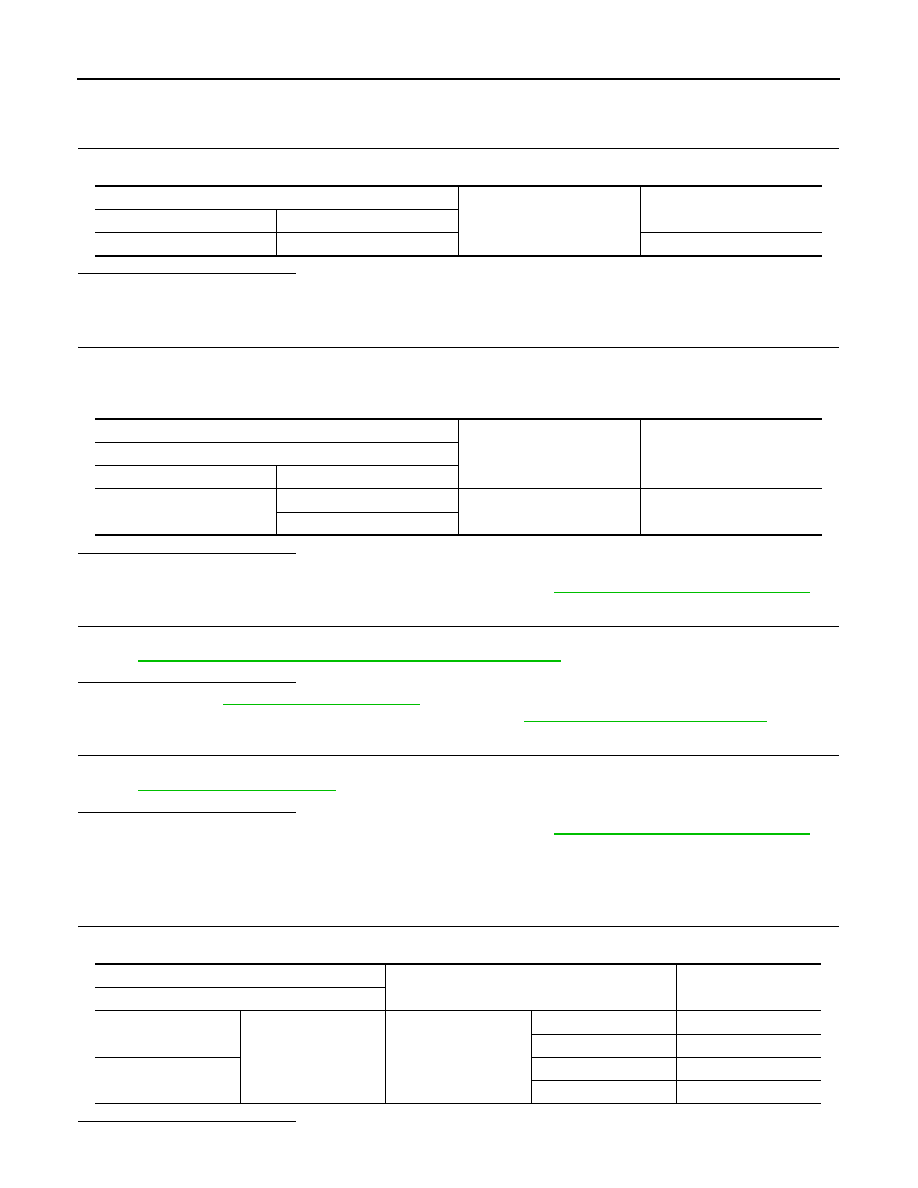
Check continuity between door mirror remote control switch connector and ground.
Is the inspection result normal?
YES
>> GO TO 4.
NO
>> Repair or replace harness.
4.
CHECK AUTOMATIC DRIVE POSITIONER CONTROL UNIT OUTPUT SIGNAL
1.
Connect automatic drive positioner control unit connector.
2.
Turn ignition switch ON.
3.
Check voltage between automatic drive positioner control unit connector and ground.
Is the inspection result normal?
YES
>> GO TO 5.
NO
>> Replace automatic drive positioner control unit. Refer to
ADP-210, "Removal and Installation"
5.
CHECK CHANGEOVER SWITCH
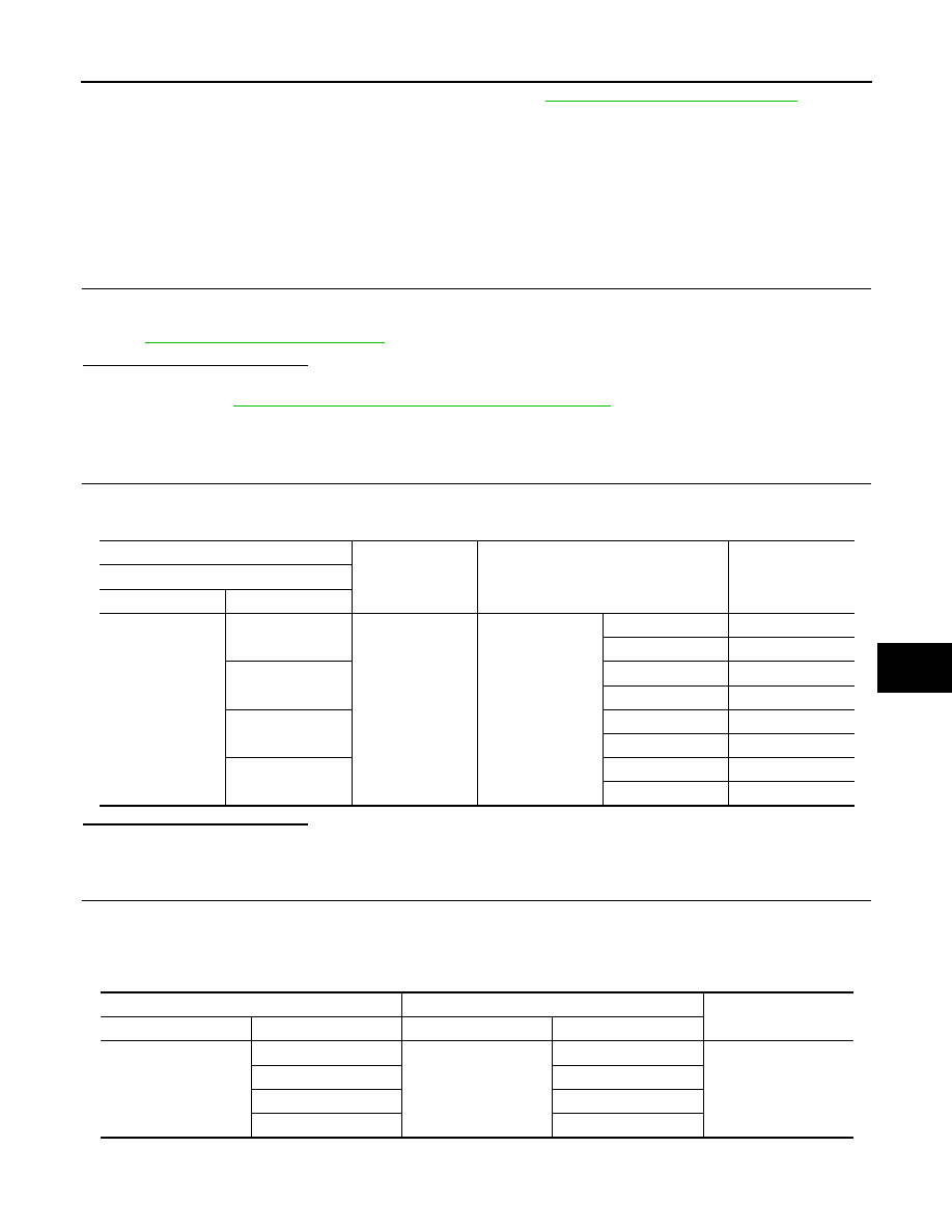
Check changeover switch.
Refer to
ADP-78, "CHANGEOVER SWITCH : Component Inspection"
.
Is the inspection result normal?
YES
>> Refer to
GI-38, "Intermittent Incident"
.
NO
>> Replace door mirror remote control switch. Refer to
MIR-56, "Removal and Installation"
6.
CHECK INTERMITTENT INCIDENT
Check intermittent incident.
Refer to
GI-38, "Intermittent Incident"
Is the inspection result normal?
YES
>> Replace automatic drive positioner control unit. Refer to
ADP-210, "Removal and Installation"
NO
>> Repair or replace the malfunctioning parts.
CHANGEOVER SWITCH : Component Inspection
INFOID:0000000003134708
1.
CHECK CHANGEOVER SWITCH
Check door mirror remote control switch.
Is the inspection result normal?
YES
>> INSPECTION END
Door mirror remote control switch
Ground
Continuity
Connector
Terminal
D17
7
Existed
(+)
(-)
Voltage (V)
(Approx.)
Automatic drive positioner control unit
Connector
Terminal
M51
2
Ground
5
18
Door mirror remote control switch
Condition
Continuity
Terminal
10
7
Change over switch
LEFT
Existed
Other than above
Not existed
11
RIGHT
Existed
Other than above
Not existed
DOOR MIRROR REMOTE CONTROL SWITCH
ADP-79
< COMPONENT DIAGNOSIS >
C
D
E
F
G
H
I
K
L
M
A
B
ADP
N
O
P
NO
>> Replace door mirror remote control switch. Refer to
MIR-56, "Removal and Installation"
MIRROR SWITCH
MIRROR SWITCH : Description
INFOID:0000000003134709
It operates angle of the door mirror face.
It transmits mirror face adjust operation to AUTOMATIC DRIVE POSITIONER CONTROL UNIT.
MIRROR SWITCH : Component Function Check
INFOID:0000000003134710
1.
CHECK MIRROR SWITCH FUNCTION
Check the operation on “MIR CON SW–UP/DN” and “MIR CON SW–RH/LH” in “DATA MONITOR” mode
with CONSULT-III.
Refer to
ADP-42, "CONSULT-III Function"
.
Is the inspection result normal?
YES
>> Mirror switch function is OK.
NO
>> Refer to
ADP-79, "MIRROR SWITCH : Diagnosis Procedure"
.
MIRROR SWITCH : Diagnosis Procedure
INFOID:0000000003134711
1.
CHECK MIRROR SWITCH FUNCTION
1.
Turn ignition switch ON.
2.
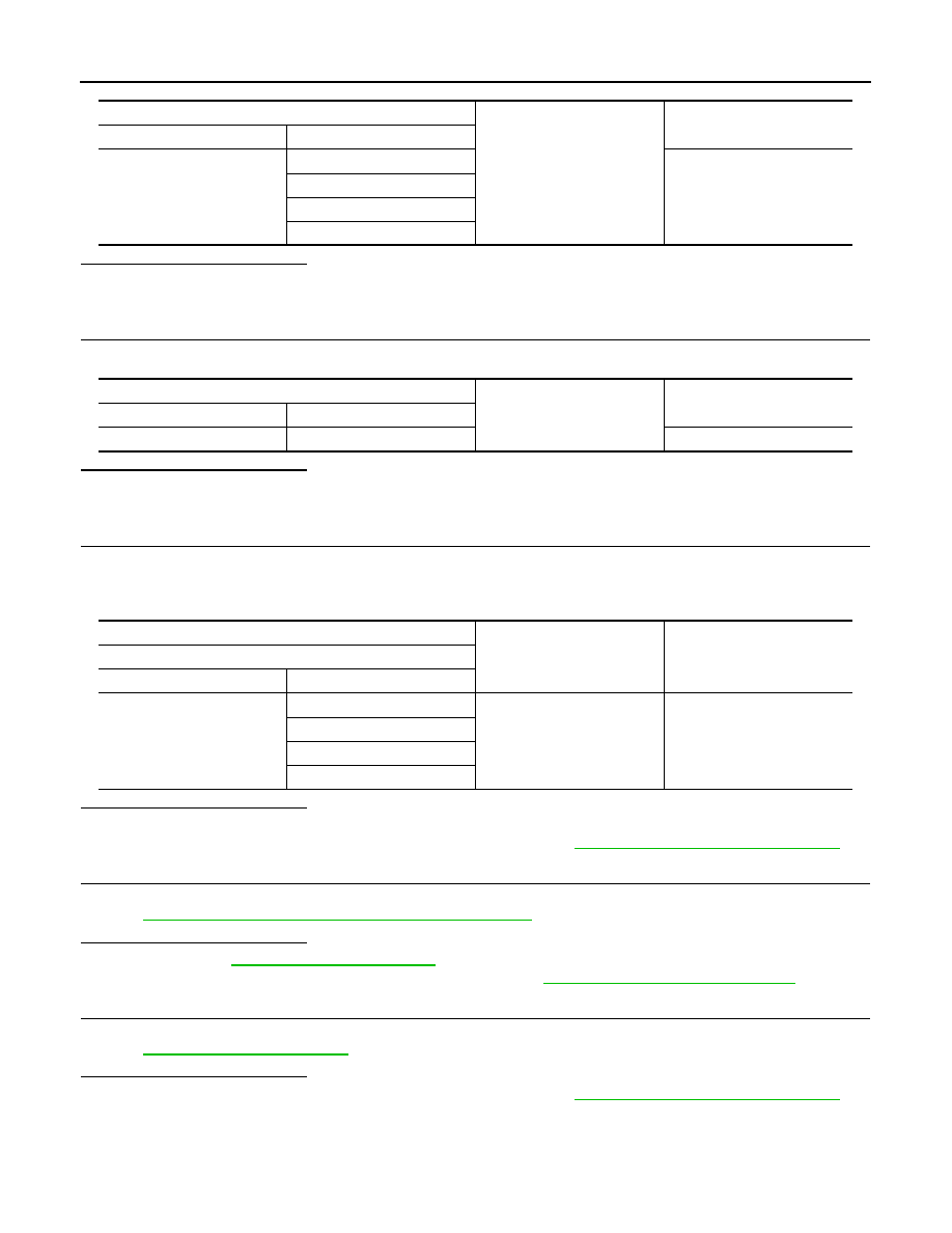
Check voltage between automatic drive positioner control unit connector and ground.
Is the inspection result normal?
YES
>> GO TO 6.
NO
>> GO TO 2.
2.
CHECK HARNESS CONTINUITY
1.
Turn ignition switch OFF.
2.
Disconnect automatic drive positioner control unit and door mirror remote control switch connector.
3.
Check continuity between automatic drive positioner control unit connector and door mirror remote control
switch connector.
4.
Check continuity between automatic drive positioner control unit connector and ground.
(+)
(–)
Condition
Voltage (V)
(Approx.)
Automatic drive positioner control unit
Connector
Terminal
M51
3
Ground
Mirror switch
UP
0
Other than above
5
4
LEFT
0
Other than above
5
19
DOWN
0
Other than above
5
20
RIGHT
0
Other than above
5
Automatic drive positioner control unit
Door mirror remote control switch
Continuity
Connector
Terminal
Connector
Terminal
M51
3
D17
15
Existed
4
13
19
12
20
4
ADP-80
< COMPONENT DIAGNOSIS >
DOOR MIRROR REMOTE CONTROL SWITCH
Is the inspection result normal?
YES
>> GO TO 3.
NO
>> Repair or replace harness.
3.
CHECK DOOR MIRROR REMOTE CONTROL SWITCH GROUND CIRCUIT
Check continuity between door mirror remote control switch connector and ground.
Is the inspection result normal?
YES
>> GO TO 4.
NO
>> Repair or replace harness.
4.
CHECK AUTOMATIC DRIVE POSITIONER CONTROL UNIT OUTPUT SIGNAL
1.
Connect automatic drive positioner control unit connector.
2.
Turn ignition switch ON.
3.
Check voltage between automatic drive positioner control unit and ground.
Is the inspection result normal?
YES
>> GO TO 5.
NO
>> Replace automatic drive positioner control unit. Refer to
ADP-210, "Removal and Installation"
5.
CHECK MIRROR SWITCH
Check mirror switch
Refer to
ADP-81, "MIRROR SWITCH : Component Inspection"
.
Is the inspection result normal?
YES
>> Refer to
GI-38, "Intermittent Incident"
.
NO
>> Replace door mirror remote control switch. Refer to
MIR-56, "Removal and Installation"
6.
CHECK INTERMITTENT INCIDENT
Check intermittent incident.
Refer to
GI-38, "Intermittent Incident"
Is the inspection result normal?
YES
>> Replace automatic drive positioner control unit. Refer to
ADP-210, "Removal and Installation"
NO
>> Repair or replace the malfunctioning parts.
Automatic drive positioner control unit
Ground
Continuity
Connector
Terminal
M51
3
Not existed
4
19
20
Door mirror remote control switch
Ground
Continuity
Connector
Terminal
D17
7
Existed
(+)
(-)
Voltage (V)
(Approx.)
Automatic drive positioner control unit
Connector
Terminal
M51
3
Ground
5
4
19
20
DOOR MIRROR REMOTE CONTROL SWITCH
ADP-81
< COMPONENT DIAGNOSIS >
C
D
E
F
G
H
I
K
L
M
A
B
ADP
N
O
P
MIRROR SWITCH : Component Inspection
INFOID:0000000003134712
1.
CHECK MIRROR SWITCH
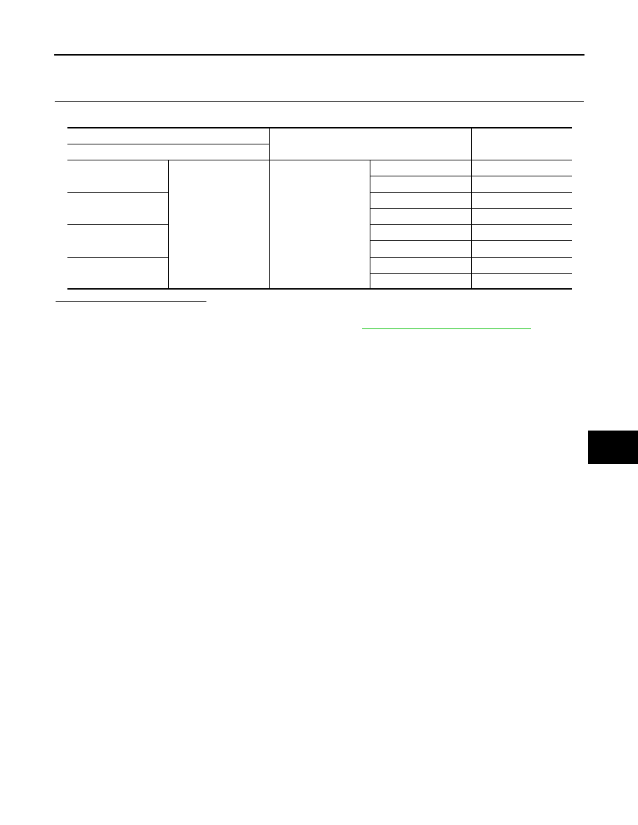
Check door mirror remote control switch.
Is the inspection result normal?
YES
>> INSPECTION END
NO
>> Replace door mirror remote control switch.Refer to
MIR-56, "Removal and Installation"
.
Door mirror remote control switch
Condition
Continuity
Terminal
4
7
Mirror switch
RIGHT
Existed
Other than above
Not existed
13
LEFT
Existed
Other than above
Not existed
15
UP
Existed
Other than above
Not existed
12
DOWN
Existed
Other than above
Not existed
Нет комментариевНе стесняйтесь поделиться с нами вашим ценным мнением.
Текст