Infiniti EX35. Manual — part 1131
PCS
IPDM E/R (INTELLIGENT POWER DISTRIBUTION MODULE ENGINE ROOM)
PCS-25
< ECU DIAGNOSIS >
[IPDM E/R]
C
D
E
F
G
H
I
J
K
L
B
A
O
P
N
74
(P)
Ground
Ignition relay power supply
Output
Ignition switch OFF
0 V
Ignition switch ON
Battery voltage
75
(Y)
Ground
Oil pressure switch
Input
Ignition
switch ON
Engine stopped
0 V
Engine running
Battery voltage
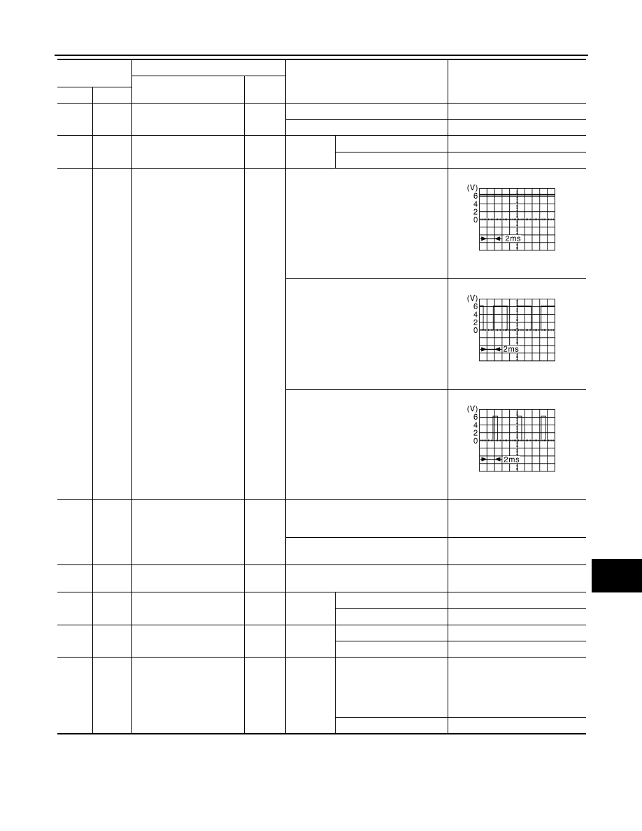
76
(V)
Ground
Power generation com-
mand signal
Output
Ignition switch ON
6.3 V
40% is set on “ACTIVE TEST”, “AL-
TERNATOR DUTY” of “ENGINE”
3.8 V
80% is set on “ACTIVE TEST”, “AL-
TERNATOR DUTY” of “ENGINE”
1.4 V
77
(L)
Ground
Fuel pump relay control
Output
• Approximately 1 second after turning
the ignition switch ON
• Engine running
0 – 1.0 V
Approximately 1 second or more after
turning the ignition switch ON
Battery voltage
80
(W)
Ground
Starter motor
Output
At engine cranking
Battery voltage
83
(O)
Ground
Headlamp LO (RH)
Output
Ignition
switch ON
Lighting switch OFF
0 V
Lighting switch 2ND
Battery voltage
84
(V)
Ground
Headlamp LO (LH)
Output
Ignition
switch ON
Lighting switch OFF
0 V
Lighting switch 2ND
Battery voltage
86
(W)
Ground
Front fog lamp (RH)
Output
Lighting
switch
2ND
• Front fog lamp switch
ON
• Daytime running light
activated (Only for Can-
ada)
Battery voltage
Front fog lamp switch OFF
0 V
Terminal No.
(Wire color)
Description
Condition
Value
(Approx.)
Signal name
Input/
Output
+
−
JPMIA0001GB
JPMIA0002GB
JPMIA0003GB

PCS-26
< ECU DIAGNOSIS >
[IPDM E/R]
IPDM E/R (INTELLIGENT POWER DISTRIBUTION MODULE ENGINE ROOM)
*: Only for the models with ICC system
87
(L)
Ground
Front fog lamp (LH)
Output
Lighting
switch
2ND
• Front fog lamp switch
ON
• Daytime running light
activated (Only for Can-
ada)
Battery voltage
Front fog lamp switch OFF
0 V
88
(GR)
Ground
Washer pump power sup-
ply
Output
Ignition switch ON
Battery voltage
89
(BR)
Ground
Headlamp HI (RH)
Output
Ignition
switch ON
• Lighting switch HI
• Lighting switch PASS
Battery voltage
Lighting switch OFF
0 V
90
(P)
Ground
Headlamp HI (LH)
Output
Ignition
switch ON
• Lighting switch HI
• Lighting switch PASS
Battery voltage
Lighting switch OFF
0 V
91
(P)
Ground
Parking lamp (RH)
Output
Ignition
switch ON
Lighting switch 1ST
Battery voltage
Lighting switch OFF
0 V
92
(O)
Ground
Parking lamp (LH)
Output
Ignition
switch ON
Lighting switch 1ST
Battery voltage
Lighting switch OFF
0 V
97
(V)
Ground
Cooling fan control
Output
Engine idling
0 – 5 V
104
(LG)
Ground
Hood switch
Input
Close the hood
Battery voltage
Open the hood
0 V
Terminal No.
(Wire color)
Description
Condition
Value
(Approx.)
Signal name
Input/
Output
+
−
PCS
IPDM E/R (INTELLIGENT POWER DISTRIBUTION MODULE ENGINE ROOM)
PCS-27
< ECU DIAGNOSIS >
[IPDM E/R]
C
D
E
F
G
H
I
J
K
L
B
A
O
P
N
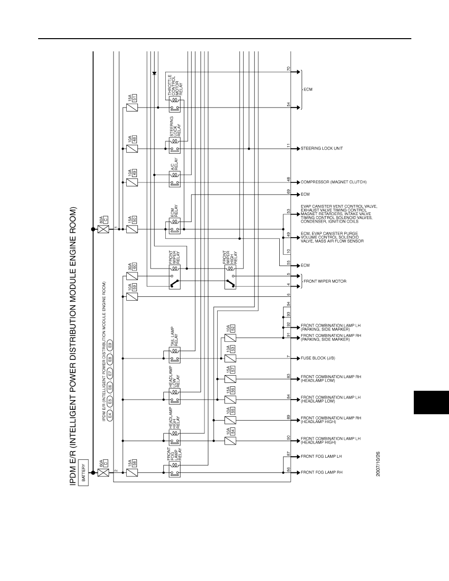
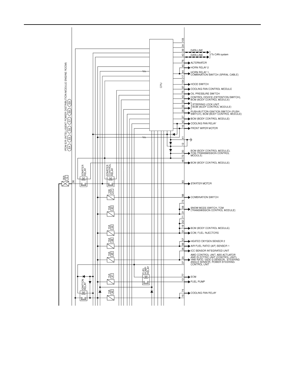
Wiring Diagram - IPDM E/R -
INFOID:0000000003132007
JCMWM1411GB
PCS-28
< ECU DIAGNOSIS >
[IPDM E/R]
IPDM E/R (INTELLIGENT POWER DISTRIBUTION MODULE ENGINE ROOM)
JCMWM1412GB
Нет комментариевНе стесняйтесь поделиться с нами вашим ценным мнением.
Текст