Infiniti EX35. Manual — part 1139

PCS
B2615 BLOWER RELAY CIRCUIT
PCS-57
< COMPONENT DIAGNOSIS >
[POWER DISTRIBUTION SYSTEM]
C
D
E
F
G
H
I
J
K
L
B
A
O
P
N
B2615 BLOWER RELAY CIRCUIT
Description
INFOID:0000000003739318
BCM controls the various electrical components and simultaneously supplies power according to the power
supply position.
BCM checks the power supply position internally.
DTC Logic
INFOID:0000000003739319
DTC DETECTION LOGIC
DTC CONFIRMATION PROCEDURE
1.
PERFORM DTC CONFIRMATION PROCEDURE
1.
Turn ignition switch ON under the following conditions, and wait for at least 1 second.
-
Selector lever is in the P or N position
-
Do not depress brake pedal
2.
Check “Self diagnostic result” with CONSULT-III.
Is DTC detected?
YES
>> Go to
NO
>> INSPECTION END
Diagnosis Procedure
INFOID:0000000003739320
1.
CHECK BLOWER RELAY POWER SUPPLY
1.
Turn ignition switch OFF.
2.
Disconnect blower relay.
3.
Check voltage between blower relay harness connector and ground.
Is the inspection result normal?
YES
>> GO TO 3.
NO
>> GO TO 2.
2.
CHECK BLOWER RELAY POWER SUPPLY CIRCUIT
1.
Turn ignition switch OFF.
2.
Disconnect BCM connector.
3.
Check continuity between blower relay harness connector and BCM harness connector.
4.
Check continuity between blower relay harness connector and ground.
DTC No.
Trouble diagnosis
name
DTC detecting condition
Possible cause
B2615
Blower relay circuit
BCM detects a difference of signal for 1 second or
more between the following information.
• Blower relay ON/OFF request
• Blower relay feedback
• Harness or connectors
(Blower relay circuit is open or
shorted)
• Blower relay
(+)
(–)
Condition
Voltage (V)
(Approx.)
Blower relay
Terminal
1
Ground
Ignition switch
OFF or ACC
0
ON
Battery voltage
Blower relay
BCM
Continuity
Terminal
Connector
Terminal
1
M122
102
Existed
PCS-58
< COMPONENT DIAGNOSIS >
[POWER DISTRIBUTION SYSTEM]
B2615 BLOWER RELAY CIRCUIT
Is the inspection result normal?
YES
>> Replace BCM. Refer to
BCS-84, "Removal and Installation"
NO
>> Repair or replace harness or connector.
3.
CHECK BLOWER RELAY GROUND CIRCUIT
1.
Turn ignition switch OFF.
2.
Check continuity between blower relay harness connector and ground.
Is the inspection result normal?
YES
>> GO TO 4.
NO
>> Repair blower relay ground circuit.
4.
CHECK BLOWER RELAY
PCS-58, "Component Inspection"
.
Is the inspection result normal?
YES
>> GO TO 5.
NO
>> Replace blower relay.
5.
CHECK INTERMITTENT INCIDENT
GI-38, "Intermittent Incident"
>> INSPECTION END
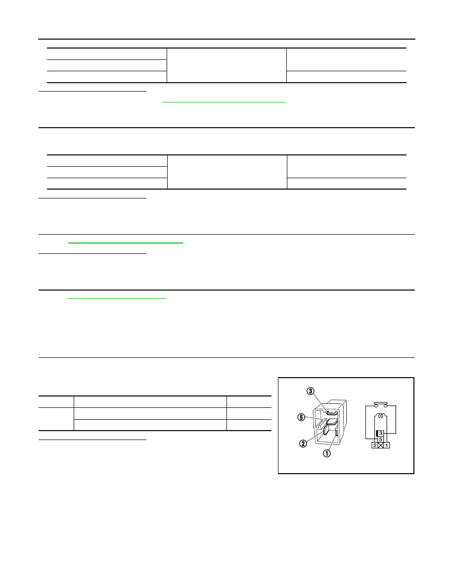
Component Inspection
INFOID:0000000003739321
1.
CHECK BLOWER RELAY
1.
Turn ignition switch OFF.
2.
Remove blower relay.
3.
Check the continuity between blower relay terminals.
Is the inspection result normal?
YES
>> INSPECTION END
NO
>> Replace blower relay
Blower relay
Ground
Continuity
Terminal
1
Not existed
Blower relay
Ground
Continuity
Terminal
2
Existed
Terminals
Condition
Continuity
3 and 5
12 V direct current supply between terminals 1 and 2
Existed
No current supply
Not existed
PBIB0098E

PCS
B2616 IGNITION RELAY CIRCUIT
PCS-59
< COMPONENT DIAGNOSIS >
[POWER DISTRIBUTION SYSTEM]
C
D
E
F
G
H
I
J
K
L
B
A
O
P
N
B2616 IGNITION RELAY CIRCUIT
Description
INFOID:0000000003739322
BCM controls the various electrical components and simultaneously supplies power according to the power
supply position.
BCM checks the power supply position internally.
DTC Logic
INFOID:0000000003739323
DTC DETECTION LOGIC
DTC CONFIRMATION PROCEDURE
1.
PERFORM DTC CONFIRMATION PROCEDURE
1.
Turn ignition switch ON under the following conditions, and wait for at least 1 second.
-
Selector lever is in the P or N position.
-
Do not depress brake pedal.
2.
Check “Self diagnostic result” with CONSULT-III.
Is DTC detected?
YES
>> Go to
NO
>> INSPECTION END
Diagnosis Procedure
INFOID:0000000003739324
1.
CHECK IGNITION RELAY POWER SUPPLY
1.
Turn ignition switch OFF.
2.
Disconnect ignition relay.
3.
Check voltage between ignition relay harness connector and ground.
Is the inspection result normal?
YES
>> GO TO 3.
NO
>> GO TO 2.
2.
CHECK IGNITION RELAY POWER SUPPLY CIRCUIT
1.
Turn ignition switch OFF.
2.
Disconnect BCM connector.
3.
Check continuity between ignition relay harness connector and BCM harness connector.
4.
Check continuity between ignition relay harness connector and ground.
DTC No.
Trouble diagnosis
name
DTC detecting condition
Possible cause
B2616
Ignition relay circuit
An immediate operation of ignition relay (fuse
block) is requested by BCM, but there is no re-
sponse for more than 1 second
• Harness or connectors
(Ignition relay circuit is open or
shorted)
• Ignition relay (Fuse block)
(+)
(–)
Condition
Voltage (V)
(Approx.)
Ignition relay
Terminal
1
Ground
Ignition switch
OFF or ACC
0
ON
Battery voltage
Ignition relay
BCM
Continuity
Terminal
Connector
Terminal
1
M122
82
Existed
PCS-60
< COMPONENT DIAGNOSIS >
[POWER DISTRIBUTION SYSTEM]
B2616 IGNITION RELAY CIRCUIT
Is the inspection result normal?
YES
>> Replace BCM. Refer to
BCS-84, "Removal and Installation"
.
NO
>> Repair or replace harness or connector.
3.
CHECK IGNITION RELAY GROUND CIRCUIT
1.
Turn ignition switch OFF.
2.
Check continuity between ignition relay harness connector and ground.
Is the inspection result normal?
YES
>> GO TO 4.
NO
>> Repair ignition relay ground circuit.
4.
CHECK IGNITION RELAY
PCS-60, "Component Inspection"
.
Is the inspection result normal?
YES
>> GO TO 5.
NO
>> Replace ignition relay.
5.
CHECK INTERMITTENT INCIDENT
GI-38, "Intermittent Incident"
>> INSPECTION END
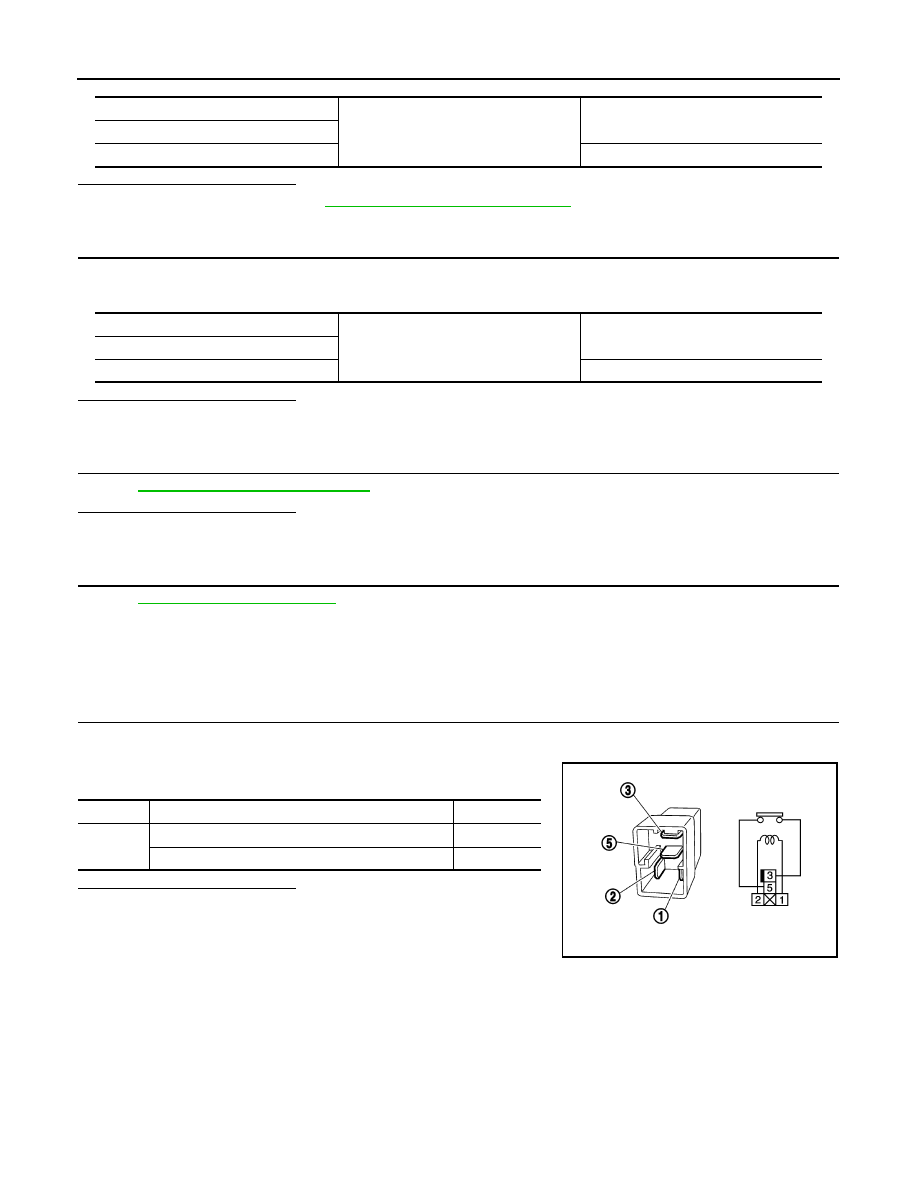
Component Inspection
INFOID:0000000003739325
1.
CHECK IGNITION RELAY
1.
Turn ignition switch OFF.
2.
Remove ignition relay.
3.
Check the continuity between ignition relay terminals.
Is the inspection result normal?
YES
>> INSPECTION END
NO
>> Replace Ignition relay
Ignition relay
Ground
Continuity
Terminal
1
Not existed
Ignition relay
Ground
Continuity
Terminal
2
Existed
Terminals
Condition
Continuity
3 and 5
12 V direct current supply between terminals 1 and 2
Existed
No current supply
Not existed
PBIB0098E
Нет комментариевНе стесняйтесь поделиться с нами вашим ценным мнением.
Текст