Infiniti EX35. Manual — part 96

AV
AUXILIARY INPUT JACKS
AV-165
< ON-VEHICLE REPAIR >
[BASE AUDIO WITHOUT NAVIGATION]
C
D
E
F
G
H
I
J
K
L
M
B
A
O
P
AUXILIARY INPUT JACKS
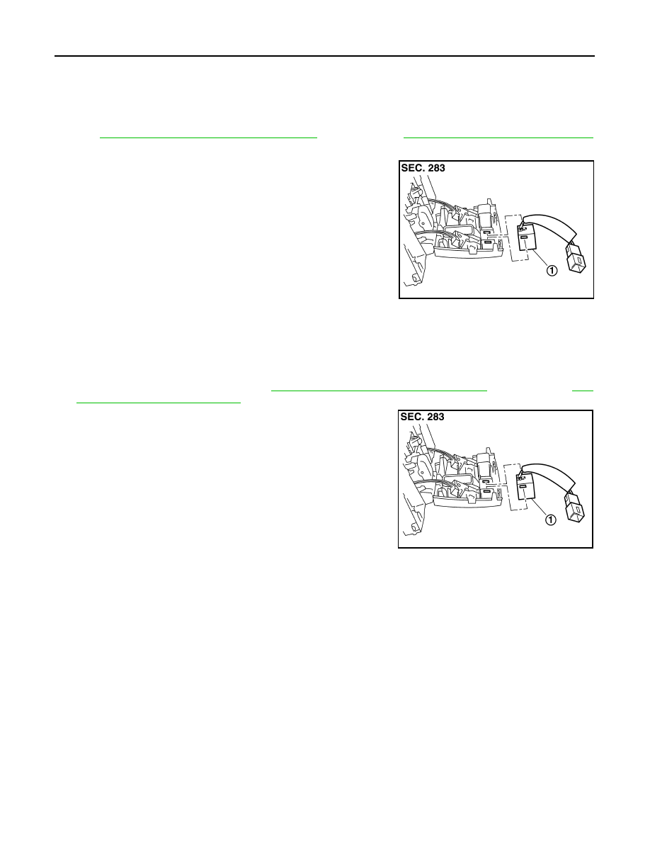
Exploded View
INFOID:0000000003573705
REMOVAL
.
DISASSEMBLY
Removal and Installation
INFOID:0000000003573706
REMOVAL
1.
Remove console finisher. Refer to
2.
Remove auxiliary mounting screws.
3.
Remove auxiliary input jacks.
INSTALLATION
Installation is the reverse order of removal.
JPNIA0882ZZ
1.
Auxiliary input jacks
AV-166
< ON-VEHICLE REPAIR >
[BASE AUDIO WITHOUT NAVIGATION]
MICROPHONE
MICROPHONE
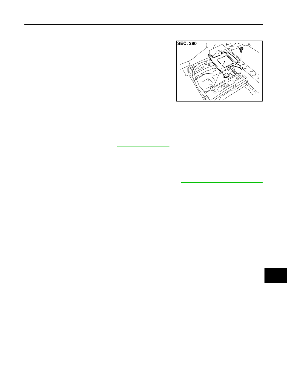
Exploded View
INFOID:0000000003573725
REMOVAL
INT-26, "NORMAL ROOF : Exploded View"
(normal roof) or
INT-30, "SUNROOF : Exploded View"
(sunroof).
DISASSEMBLY
Removal and Installation
INFOID:0000000003573726
REMOVAL
1.
Remove map lamp assembly. Refer to
INT-26, "NORMAL ROOF : Exploded View"
(sunroof).
2.
Remove microphone (1), stretching pawls of map lamp assem-
bly.
INSTALLATION
Installation is the reverse order of removal.
JSNIA0132ZZ
1.
Microphone
JSNIA0132ZZ
AV
CAMERA CONTROL UNIT
AV-167
< ON-VEHICLE REPAIR >
[BASE AUDIO WITHOUT NAVIGATION]
C
D
E
F
G
H
I
J
K
L
M
B
A
O
P
CAMERA CONTROL UNIT
Exploded View
INFOID:0000000003573730
Removal and Installation
INFOID:0000000003573731
REMOVAL
1.
Remove front seat (LH side). Refer to
.
2.
Remove floor carpet. Keep a service area.
3.
Remove camera control unit.
INSTALLATION
1.
Installation is the reverse order of removal.
2.
Perform predicted course line center position adjustment. Refer to
CENTER POSITION ADJUSTMENT : Special Repair Requirement"
JPNIA0883ZZ
1.
Camera control unit

AV-168
< ON-VEHICLE REPAIR >
[BASE AUDIO WITHOUT NAVIGATION]
REAR VIEW CAMERA
REAR VIEW CAMERA
Exploded View
INFOID:0000000003573733
DISASSEMBLY
Removal and Installation
INFOID:0000000003573734
REMOVAL
1.
Remove back door finisher inner. Refer to
2.
Remove back door outside finisher upper. Refer to
3.
Remove back door outside finisher lower. Refer to
.
4.
Remove rear view camera mounting screws and rear view camera harness connector.
5.
Remove rear view camera.
INSTALLATION
1.
Installation is the reverse order of removal.
2.
Adjust the guide line position if the guide line position is shifted after installing the rear view camera. Refer
to
.
JPNIA0884ZZ
1.
Rear view camera
Нет комментариевНе стесняйтесь поделиться с нами вашим ценным мнением.
Текст