Infiniti EX35. Manual — part 751

E X L - 4 8
< COMPONENT DIAGNOSIS >
[XENON TYPE]
B2503, B2504 SWIVEL ACTUATOR
1.
Turn the ignition switch OFF.
2.
Disconnect AFS control unit connector.
3.
Check continuity between the AFS control unit harness connector and the headlamp swivel actuator har-
ness connector.
Does continuity exist?
YES
>> Replace the front combination lamp.
NO
>> Repair the harnesses or connectors.
9.
CHECK SWIVEL POSITION SENSOR GROUND CIRCUIT VOLTAGE OUTPUT
Check the voltage between the AFS control unit harness connector and the ground.
Is the measurement value normal?
YES
>> GO TO 10.
NO
>> Replace AFS control unit.
10.
CHECK SWIVEL POSITION SENSOR SHORT GROUND CIRCUIT
1.
Turn the ignition switch OFF.
2.
Disconnect AFS control unit connector and the headlamp swivel actuator connector.
3.
Check continuity between the AFS control unit harness connector and the headlamp swivel actuator har-
ness connector.
Does continuity exist?
YES
>> Replace the front combination lamp.
NO
>> Repair the harnesses or connectors.
Component Inspection
INFOID:0000000003135297
1.
CHECK SWIVEL MOTOR SINGLE PART
1.
Disconnect the swivel actuator connector.
2.
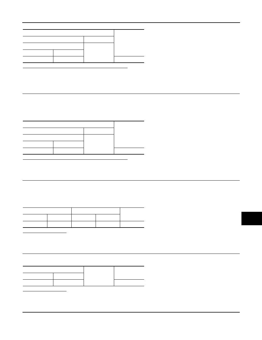
Check the resistance among each swivel actuator connector terminal.
AFS control unit
Headlamp swivel actuator
Continuity
Connector
Terminal
Connector
Terminal
RH
M16
9
E29
1
Existed
LH
29
E59
1
Terminals
Voltage
(Approx.)
(+)
(
−
)
AFS control unit
Ground
Connector
Terminal
RH
M16
2
0 V
LH
27
AFS control unit
Headlamp swivel actuator
Continuity
Connector
Terminal
Connector
Terminal
RH
M16
2
E29
6
Existed
LH
27
E59
6
Swivel actuator
Resistance
(Approx.)
Terminal
Terminal
3
7
7.2
Ω
4
8
7.2
Ω
3
4
10 M
Ω
or more
B2503, B2504 SWIVEL ACTUATOR
EXL-49
< COMPONENT DIAGNOSIS >
[XENON TYPE]
C
D
E
F
G
H
I
J
K
M
A
B
EXL
N
O
P
Is the measurement value normal?
YES
>> Swivel actuator is normal.
NO
>> Replace the front combination lamp.

EXL-50
< COMPONENT DIAGNOSIS >
[XENON TYPE]
B2514 HEIGHT SENSOR UNUSUAL [RR]
B2514 HEIGHT SENSOR UNUSUAL [RR]
Description
INFOID:0000000003135298
The height sensor is installed to the rear suspension arm. The height sensor detects the suspension arm dis-
placement as the vehicle height change. The height sensor transmits the height sensor signal to AFS control
unit.
NOTE:
The sensor angle of the unloaded vehicle position is the reference value.
DTC Logic
INFOID:0000000003135299
DTC DETECTION LOGIC
[B2514] Height sensor unusual [RR]
DTC CONFIRMATION PROCEDURE
1.
DTC ERASE
Erase the DTC memory of AFS with CONSULT-III.
>> GO TO 2.
2.
DTC CONFIRMATION
1.
Start the engine.
2.
Turn the headlamp ON.
3.
Select the self-diagnosis with CONSULT-III.
4.
Check the self-diagnosis result. Refer to
Is "B2514" detected?
YES
>> Refer to
.
NO
>> Refer to
GI-38, "Intermittent Incident"
.
Diagnosis Procedure
INFOID:0000000003135300
1.
CHECK HEIGHT SENSOR POWER SUPPLY OUTPUT
1.
Turn the ignition switch ON.
2.
Check the voltage between the AFS control unit harness connector and the ground.
Is the measurement value within the standard value?
YES
>> GO TO 2.
NO
>> Replace AFS control unit.
2.
CHECK HEIGHT SENSOR POWER SUPPLY INPUT
Check the voltage between the AFS control unit harness connector and the ground.
DTC detection condition
DTC erase condition
Possible cause
An applicable DTC is indicated when any of the following
conditions is detected continuously for 2 seconds or more.
• The height sensor power supply is 6 V or more, or 4 V or
less.
• The height sensor signal is 0.25 V or less, or 4.75 V or
more.
Ignition switch OFF
Height sensor
• Height sensor
• Harness and connector
• AFS control unit
Terminals
Voltage
(Approx.)
(+)
(
−
)
AFS control unit
Ground
Connector
Terminal
M16
6
5 V
B2514 HEIGHT SENSOR UNUSUAL [RR]
EXL-51
< COMPONENT DIAGNOSIS >
[XENON TYPE]
C
D
E
F
G
H
I
J
K
M
A
B
EXL
N
O
P
Is the measurement value within the standard value?
YES
>> Replace AFS control unit.
Less than the standard value >>GO TO 3.
Higher than the standard value>>GO TO 6.
3.
CHECK HEIGHT SENSOR POWER SUPPLY CIRCUIT OUTPUT VOLTAGE
1.
Turn the ignition switch OFF.
2.
Disconnect the height sensor connector.
3.
Turn the ignition switch ON.
4.
Check the voltage between the height sensor harness connector and the ground.
Is the measurement value within the standard value?
YES
>> GO TO 4.
NO
>> Repair the harnesses or connectors.
4.
CHECK HEIGHT SENSOR SIGNAL OPEN CIRCUIT
1.
Turn the ignition switch OFF.
2.
Disconnect AFS control unit connector.
3.
Check continuity between the AFS control unit harness connector and the height sensor harness connec-
tor.
Does continuity exist?
YES
>> GO TO 5.
NO
>> Repair the harnesses or connectors.
5.
CHECK HEIGHT SENSOR SIGNAL SHORT CIRCUIT
Check continuity between the height sensor harness connector and the ground.
Does continuity exist?
YES
>> Repair the harnesses or connectors.
NO
>> Replace the height sensor.
6.
CHECK HEIGHT SENSOR GROUND
Check the voltage between the AFS control unit harness connector and the ground.
Terminals
Voltage
(Approx.)
(+)
(
−
)
AFS control unit
Ground
Connector
Terminal
M16
28
0.25 - 4.75 V
Terminals
Voltage
(Approx.)
(+)
(
−
)
Height sensor
Ground
Connector
Terminal
B32
1
5 V
AFS control unit
Height sensor
Continuity
Connector
Terminal
Connector
Terminal
M16
28
B32
2
Existed
Height sensor
Ground
Continuity
Connector
Terminal
B32
2
Not existed
Нет комментариевНе стесняйтесь поделиться с нами вашим ценным мнением.
Текст