Infiniti EX35. Manual — part 1485
VTL-58
< ON-VEHICLE REPAIR >
DUCT AND GRILLE
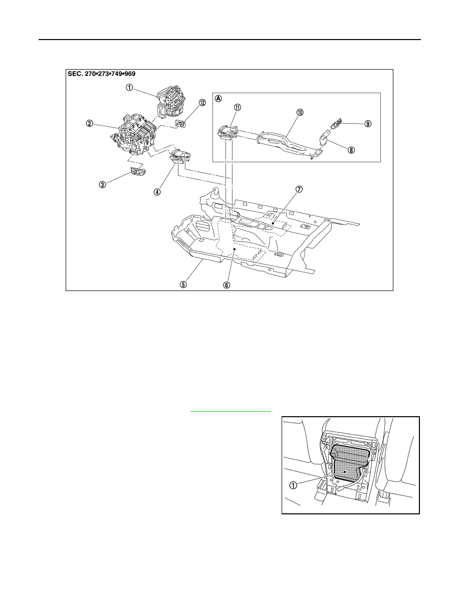
REAR VENTILATOR DUCT 2 : Exploded View
INFOID:0000000003567133
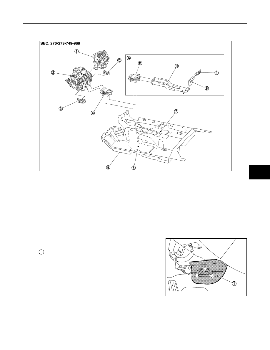
REAR VENTILATOR DUCT 2 : Removal and Installation
INFOID:0000000003567132
REMOVAL
1.
Remove console rear finisher. Refer to
.
2.
Remove rear ventilator duct 2 (1).
INSTALLATION
Installation is basically the reverse order of removal.
FOOT GRILLE
1.
Blower unit
2.
Heater & cooling unit assembly
3.
Foot grille (left)
4.
Rear floor duct 1 (without rear venti-
lation)
5.
Floor carpet
6.
Rear floor duct 2 (left)
7.
Rear floor duct 2 (right)
8.
Rear ventilator duct 2
9.
Rear ventilator grille
10. Rear ventilator duct 1
11. Rear floor duct 1 (with rear ventila-
tion)
12. Foot grille (right)
A.
With rear ventilation
JPIIA0676ZZ
JPIIA0679ZZ
DUCT AND GRILLE
VTL-59
< ON-VEHICLE REPAIR >
C
D
E
F
G
H
J
K
L
M
A
B
VTL
N
O
P
FOOT GRILLE : Exploded View
INFOID:0000000003567130
FOOT GRILLE : Removal and Installation
INFOID:0000000003545439
REMOVAL
1.
Remove foot grille (left) (1).
2.
Remove foot grille (right) (1).
1.
Blower unit
2.
Heater & cooling unit assembly
3.
Foot grille (left)
4.
Rear floor duct 1 (without rear venti-
lation)
5.
Floor carpet
6.
Rear floor duct 2 (left)
7.
Rear floor duct 2 (right)
8.
Rear ventilator duct 2
9.
Rear ventilator grille
10. Rear ventilator duct 1
11. Rear floor duct 1 (with rear ventila-
tion)
12. Foot grille (right)
A.
With rear ventilation
JPIIA0676ZZ
:
Pawl
JPIIA0682ZZ

VTL-60
< ON-VEHICLE REPAIR >
DUCT AND GRILLE
INSTALLATION
Installation is basically the reverse order of removal.
FOOT DUCT
FOOT DUCT : Exploded View
INFOID:0000000003567108
:
Pawl
JPIIA0683ZZ
JPIIA0649GB
DUCT AND GRILLE
VTL-61
< ON-VEHICLE REPAIR >
C
D
E
F
G
H
J
K
L
M
A
B
VTL
N
O
P
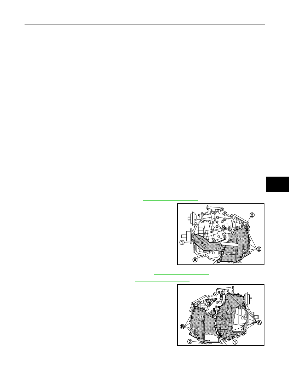
FOOT DUCT : Removal and Installation
INFOID:0000000003545441
REMOVAL
1.
Remove heater & cooling unit assembly. Refer to
.
2.
Remove mounting screws (A), and then remove heater pipe
cover (1).
3.
Remove mounting screws (B), and then remove foot duct (left)
(2).
4.
Remove air mix door motor (passenger side). Refer to
.
5.
Remove mode door motor and links. Refer to
.
6.
Remove mounting screws (A), and then remove evaporator
cover (1).
7.
Remove mounting screws (B), and then remove foot duct (right)
(2).
INSTALLATION
Installation is basically the reverse order of removal.
1.
Ventilator seal
2.
Ventilator door
3.
Defroster seal
4.
Packing
5.
Defroster door (right)
6.
Packing
7.
Foot duct (right)
8.
Ventilator door spring
9.
Ventilator door lever
10.
Foot door lever
11.
Foot door link
12. Main link sub
13.
Ventilator door link
14.
Main link
15. Mode door motor bracket
16.
Mode door motor
17.
Evaporator cover
18. Low-pressure pipe 1
19.
Cooler pipe grommet
20.
High-pressure pipe 2
21. O-ring
22.
Expansion valve
23.
Evaporator
24. Insulator
25.
Drain hose
26.
Clamp
27. Evaporator cover adapter
28.
Heater pipe bracket
29.
Heater pipe grommet
30. Heater core
31.
Heater pipe cover
32.
Packing
33. Case packing
34.
Heater & cooling unit case (left)
35.
Air mix door adapter
36. Air mix door motor (driver side)
*
37.
J-nut
38.
Front heater duct
39. Aspirator hose
40.
Aspirator
41.
Foot duct (left)
42. Defroster door (left)
43.
Packing
44.
Center case
45. Foot door (left)
46.
Rear ventilator door
47.
Foot door (right)
48. J-nut
49.
Max. cool door lever
50.
Defroster door lever
51. Defroster door link
52.
Max. cool door link
53.
Intake sensor
54. Intake sensor bracket
55.
Air mix door motor (passenger side)
56.
Air mix door adapter
57. Heater & cooling unit case (right)
58.
Max. cool door (right)
59.
Max. cool door (left)
60. Air mix door (Slide door)
*With left and right ventilation temperature separately system.
Refer to
for symbols in the figure.
JSIIA1114ZZ
JSIIA1115ZZ
Нет комментариевНе стесняйтесь поделиться с нами вашим ценным мнением.
Текст