Infiniti EX35. Manual — part 1257
MOTOR SENSOR
SE-35
< COMPONENT DIAGNOSIS >
C
D
E
F
G
H
I
K
L
M
A
B
SE
N
O
P
YES
>> Motor sensor (LH) is OK.
NO
>> Repair or replace harness.
3.
CHECK MOTOR SENSOR (LH) POWER SUPPLY
Check voltage between power return motor assembly (LH) harness connector and ground.
Is the inspection result normal?
YES
>> GO TO 5.
NO
>> GO TO 4.
4.
CHECK MOTOR SENSOR (LH) POWER SUPPLY CIRCUIT
1.
Disconnect power return motor assembly (LH) connector and rear seatback power return control unit con-
nector.
2.
Check continuity between rear seatback power return control unit harness connector and power return
motor assembly (LH) harness connector.
3.
Check continuity between rear seatback power return control unit harness connector and ground.
Is the inspection result normal?
YES
>> Replace rear seatback power return control unit. Refer to
SE-105, "Removal and Installation"
NO
>> Repair or replace harness.
5.
CHECK MOTOR SENSOR (LH) GROUND CIRCUIT
1.
Disconnect power return motor assembly (LH) connector and rear seatback power return control unit con-
nector.
2.
Check continuity between power return motor assembly harness connector and ground.
Is the inspection result normal?
YES
>> Replace motor sensor (LH) [reclining device assembly (LH)]. Refer to
.
NO
>> Repair or replace harness.
RH
RH : Description
INFOID:0000000003642195
Detect the operation condition of power return motor (RH).
RH : Component Function Check
INFOID:0000000003642196
1.
CHECK FUNCTION
Check that the rear seatback (RH) rises when pressing and holding the power return switch (RH) or rear seat-
back switch (RH) in UP direction.
(+)
(–)
Condition
Voltage (V)
(Approx.)
Power return motor assembly (LH)
Connector
Terminal
B511
3
Ground
When the power return motor is operated
Battery voltage
Rear seatback power return control unit
Power return motor assembly (LH)
Continuity
Connector
Terminal
Connector
Terminal
B227
11
B511
3
Existed
Rear seatback power return control unit
Ground
Continuity
Connector
Terminal
B227
11
Not existed
Rear seatback power return control unit
Power return motor assembly (LH)
Continuity
Connector
Terminal
Connector
Terminal
B227
9
B511
5
Existed
SE-36
< COMPONENT DIAGNOSIS >
MOTOR SENSOR
Is the inspection result normal?
YES
>> Motor sensor (RH) is OK.
NO
>> Refer to
SE-36, "RH : Diagnosis Procedure"
.
RH : Diagnosis Procedure
INFOID:0000000003642197
1.
CHECK MOTOR SENSOR (RH) OUTPUT SIGNAL
1.
Turn ignition switch OFF.
2.
Check voltage between power return motor assembly (RH) harness connector and ground.
Is the inspection result normal?
YES
>> GO TO 2.
NO
>> GO TO 3.
2.
CHECK MOTOR SENSOR (RH) SIGNAL CIRCUIT
1.
Disconnect power return motor assembly (RH) connector and rear seatback power return control unit con-
nector.
2.
Check continuity between power return motor assembly (RH) harness connector and rear seatback power
return control unit harness connector.
3.
Check continuity between power return motor assembly (RH) harness connector and ground.
Is the inspection result normal?
YES
>> Motor sensor (RH) is OK.
NO
>> Repair or replace harness.
3.
CHECK MOTOR SENSOR (RH) POWER SUPPLY
Check voltage between power return motor assembly (RH) harness connector and ground.
Is the inspection result normal?
YES
>> GO TO 5.
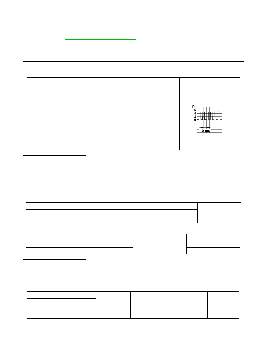
(+)
(–)
Condition
Voltage (V)
(Approx.)
Power return motor assembly (RH)
Connector
Terminal
B504
18
Ground
During the power return motor
(RH) operation
When pinching between LH/RH
seats occurs
The above pulse width should be
expanded
JMKIA0070GB
Rear seatback power return control unit
Power return motor assembly (RH)
Continuity
Connector
Terminal
Connector
Terminal
B227
2
B504
18
Existed
Rear seatback power return control unit
Ground
Continuity
Connector
Terminal
B227
2
Not existed
(+)
(–)
Condition
Voltage (V)
(Approx.)
Power return motor assembly (RH)
Connector
Terminal
B504
17
Ground
When the power return motor is operated
Battery voltage

MOTOR SENSOR
SE-37
< COMPONENT DIAGNOSIS >
C
D
E
F
G
H
I
K
L
M
A
B
SE
N
O
P
NO
>> GO TO 4.
4.
CHECK MOTOR SENSOR (RH) POWER SUPPLY CIRCUIT
1.
Disconnect power return motor assembly (RH) connector and rear seatback power return control unit con-
nector.
2.
Check continuity between rear seatback power return control unit harness connector and power return
motor assembly (RH) harness connector.
3.
Check continuity between rear seatback power return control unit harness connector and ground.
Is the inspection result normal?
YES
>> Replace rear seatback power return control unit. Refer to
SE-105, "Removal and Installation"
NO
>> Repair or replace harness.
5.
CHECK MOTOR SENSOR (RH) GROUND CIRCUIT
1.
Disconnect power return motor assembly (RH) connector and rear seatback power return control unit con-
nector.
2.
Check continuity between power return motor assembly harness connector and ground.
Is the inspection result normal?
YES
>> Replace motor sensor (RH) [reclining device assembly (RH)]. Refer to
.
NO
>> Repair or replace harness.
Rear seatback power return control unit
Power return motor assembly (RH)
Continuity
Connector
Terminal
Connector
Terminal
B227
3
B504
17
Existed
Rear seatback power return control unit
Ground
Continuity
Connector
Terminal
B227
3
Not existed
Rear seatback power return control unit
Power return motor assembly (RH)
Continuity
Connector
Terminal
Connector
Terminal
B227
1
B504
19
Existed
SE-38
< COMPONENT DIAGNOSIS >
POWER RETURN MOTOR
POWER RETURN MOTOR
LH
LH : Description
INFOID:0000000003642198
Operate the rear seatback.
LH : Component Function Check
INFOID:0000000003642199
1.
CHECK FUNCTION
Check that the rear seatback (LH) rises when pressing and holding the power return switch (LH) or rear seat-
back switch (LH) in UP direction.
Is the inspection result normal?
YES
>> Power return motor (LH) is OK.
NO
>> Refer to
SE-38, "LH : Diagnosis Procedure"
LH : Diagnosis Procedure
INFOID:0000000003642200
1.
CHECK POWER RETURN MOTOR (LH) INPUT SIGNAL
1.
Turn ignition switch OFF.
2.
Check voltage between power return motor assembly (LH) harness connector and ground.
Is the inspection result normal?
YES
>> Replace power return motor assembly (LH) [reclining device assembly (LH)]. Refer to
.
NO
>> GO TO 2.
2.
CHECK POWER RETURN MOTOR (LH) CIRCUIT
1.
Disconnect rear seatback power return control unit connector and power return motor assembly (LH) con-
nector.
2.
Check continuity between rear seatback power return control unit harness connector and power return
motor assembly (LH) harness connector.
3.
Check continuity between rear seatback power return control unit harness connector and ground.
Is the inspection result normal?
(+)
(–)
Condition
Voltage (V)
(Approx.)
Power return motor assembly (LH)
Connector
Terminal
B511
1
Ground
During the power return motor (LH) reverse
operation
Battery voltage
Other than the above
0
2
During the power return motor (LH) return
operation
Battery voltage
Other than the above
0
Rear seatback power return control unit
Power return motor assembly (LH)
Continuity
Connector
Terminal
Connector
Terminal
B227
5
B511
1
Existed
6
2
Rear seatback power return control unit
Ground
Continuity
Connector
Terminal
B227
5
Not existed
6
Нет комментариевНе стесняйтесь поделиться с нами вашим ценным мнением.
Текст