Infiniti EX35. Manual — part 914
HAC-52
< FUNCTION DIAGNOSIS >
[AUTOMATIC AIR CONDITIONER]
BLOWER MOTOR CONTROL SYSTEM
BLOWER MOTOR CONTROL SYSTEM
WITHOUT LEFT AND RIGHT VENTILATION TEMPERATURE SEPARATELY
CONTROL SYSTEM
WITHOUT LEFT AND RIGHT VENTILATION TEMPERATURE SEPARATELY CON-
TROL SYSTEM : System Diagram
INFOID:0000000003545597
WITHOUT LEFT AND RIGHT VENTILATION TEMPERATURE SEPARATELY CON-
TROL SYSTEM : System Description
INFOID:0000000003545598
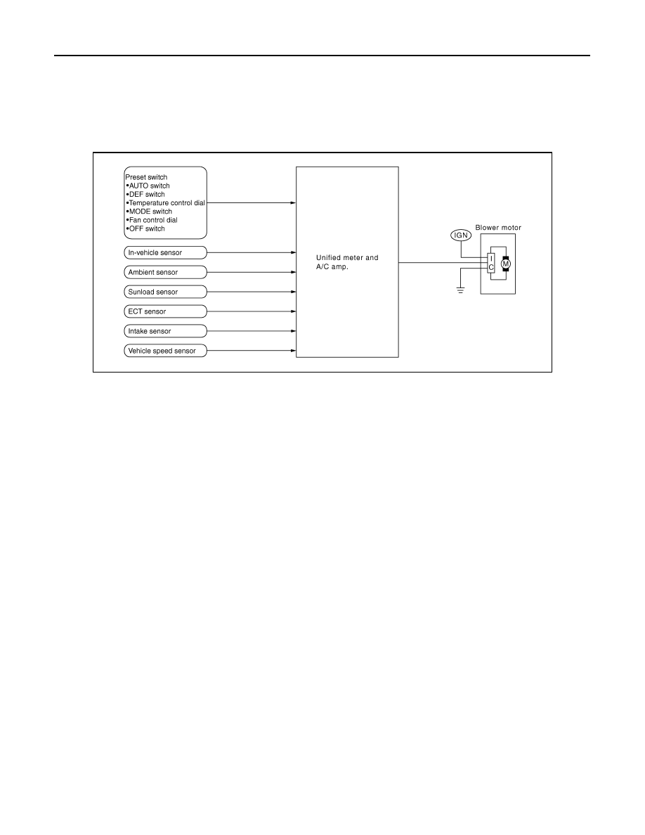
Blower speed is automatically controlled by the temperature setting, ambient temperature, in-vehicle tempera-
ture, intake temperature, amount of sunload and air mix door position.
With pressing AUTO switch, the blower motor starts to gradually increase air flow volume.
When engine coolant temperature is low, the blower motor operation is delayed to prevent cool air from flow-
ing.
SYSTEM OPERATION
Automatic Mode
In the automatic mode, the blower motor speed is calculated by the unified meter and A/C amp. based on the
input from the PBR, in-vehicle sensor, sunload sensor, intake sensor and ambient sensor.
When the air flow is increased, the duty ratio of the blower fan motor’s drive signal is changed at 8%/sec. to
prevent a sudden increase in air flow.
In addition to manual air flow control and the usual automatic air flow control, starting air flow control, low
water temperature starting control and high passenger compartment temperature starting control are avail-
able.
Starting Fan Speed Control
Start up from COLD SOAK Condition (Automatic mode)
In a cold start up condition where the engine coolant temperature is below 56
°
C (133
°
F), the blower does not
operate for a short period of time (up to 150 seconds). The exact start delay time varies depending on the
ambient and engine coolant temperature.
In the most extreme case (very low ambient) the blower start delay is 150 seconds as described above. After
this delay, the blower will operate at low speed until the engine coolant temperature rises above 56
°
C (133
°
F),
and then the blower speed increases to the objective speed.
Start up from usual or HOT SOAK Condition (Automatic mode)
The blower will begin operation momentarily after the AUTO switch is pressed. The blower speed rises gradu-
ally to the objective speed over a time period of 3 seconds or less (actual time depends on the objective
blower speed).
Blower Speed Compensation
Sunload
JSIIA1050GB
BLOWER MOTOR CONTROL SYSTEM
HAC-53
< FUNCTION DIAGNOSIS >
[AUTOMATIC AIR CONDITIONER]
C
D
E
F
G
H
J
K
L
M
A
B
HAC
N
O
P
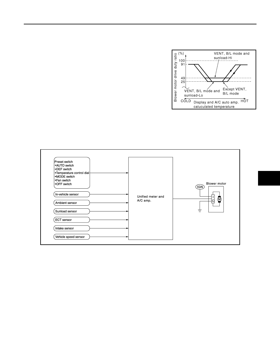
When the in-vehicle temperature and the set temperature are very close, the blower operates at low speed.
The low speed varies depending on the sunload. During conditions of low or no sunload, the blower speed is
at duty ratio 25%. During high sunload conditions, the unified meter and A/C amp. raise the blower speed
(duty ratio 49%).
Fan Speed Control Specification
WITH LEFT AND RIGHT VENTILATION TEMPERATURE SEPARATELY CON-
TROL SYSTEM
WITH LEFT AND RIGHT VENTILATION TEMPERATURE SEPARATELY CONTROL
SYSTEM : System Diagram
INFOID:0000000003545599
WITH LEFT AND RIGHT VENTILATION TEMPERATURE SEPARATELY CONTROL
SYSTEM : System Description
INFOID:0000000003545600
Blower speed is automatically controlled by the temperature setting, ambient temperature, in-vehicle tempera-
ture, intake temperature, amount of sunload and air mix door position.
With pressing AUTO switch, the blower motor starts to gradually increase air flow volume.
When engine coolant temperature is low, the blower motor operation is delayed to prevent cool air from flow-
ing.
SYSTEM OPERATION
Automatic Mode
In the automatic mode, the blower motor speed is calculated by the unified meter and A/C amp. based on the
input from the PBR, in-vehicle sensor, sunload sensor, intake sensor and ambient sensor.
When the air flow is increased, the duty ratio of the blower fan motor’s drive signal is changed at 8%/sec. to
prevent a sudden increase in air flow.
RJIA1609E
JSIIA1051GB
HAC-54
< FUNCTION DIAGNOSIS >
[AUTOMATIC AIR CONDITIONER]
BLOWER MOTOR CONTROL SYSTEM
In addition to manual air flow control and the usual automatic air flow control, starting air flow control, low
water temperature starting control and high passenger compartment temperature starting control are avail-
able.
Starting Fan Speed Control
Start up from COLD SOAK Condition (Automatic mode)
In a cold start up condition where the engine coolant temperature is below 56
°
C (133
°
F), the blower does not
operate for a short period of time (up to 150 seconds). The exact start delay time varies depending on the
ambient and engine coolant temperature.
In the most extreme case (very low ambient) the blower start delay is 150 seconds as described above. After
this delay, the blower will operate at low speed until the engine coolant temperature rises above 56
°
C (133
°
F),
and then the blower speed increases to the objective speed.
Start up from usual or HOT SOAK Condition (Automatic mode)
The blower will begin operation momentarily after the AUTO switch is pressed. The blower speed rises gradu-
ally to the objective speed over a time period of 3 seconds or less (actual time depends on the objective
blower speed).
Blower Speed Compensation
Sunload
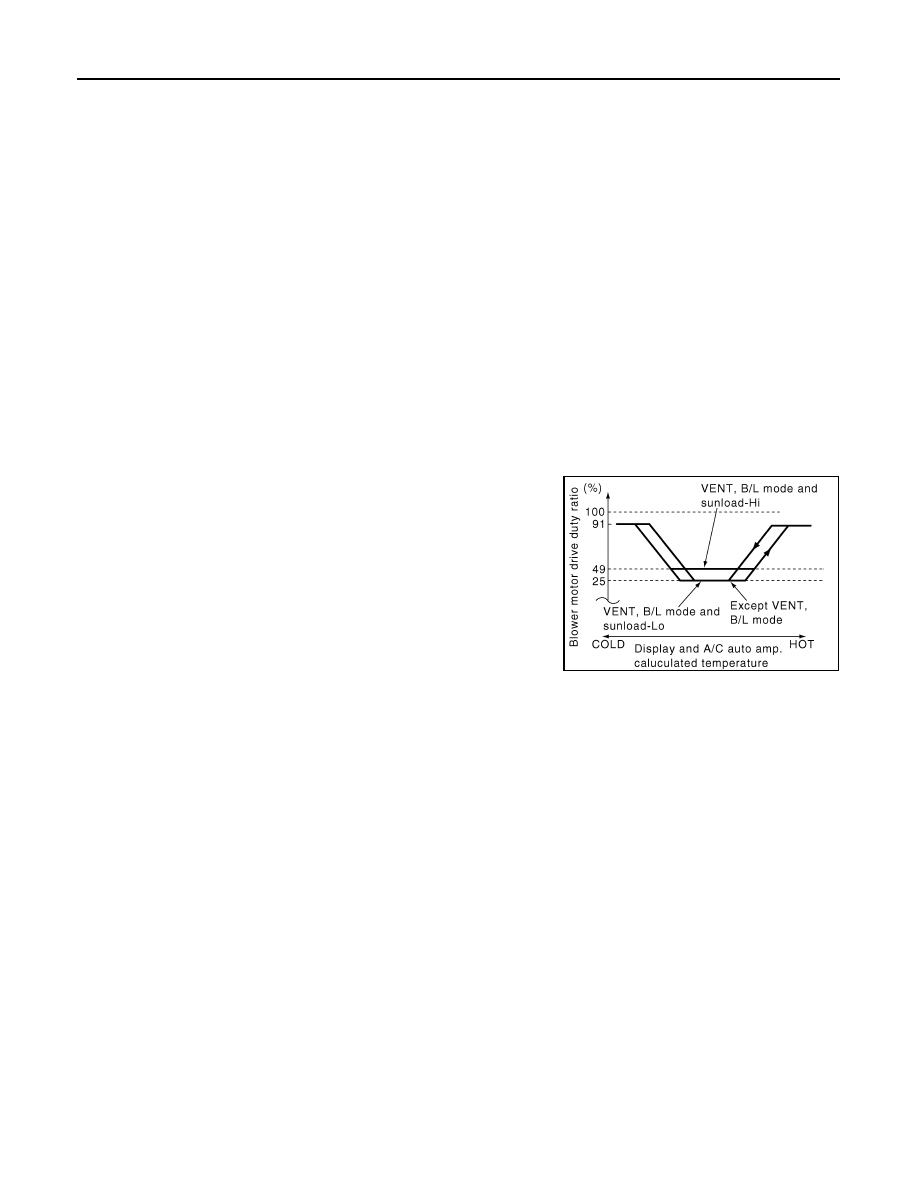
When the in-vehicle temperature and the set temperature are very close, the blower operates at low speed.
The low speed varies depending on the sunload. During conditions of low or no sunload, the blower speed is
at duty ratio 25%. During high sunload conditions, the unified meter and A/C amp. raise the blower speed
(duty ratio 49%).
Fan Speed Control Specification
RJIA1609E
MAGNET CLUTCH CONTROL SYSTEM
HAC-55
< FUNCTION DIAGNOSIS >
[AUTOMATIC AIR CONDITIONER]
C
D
E
F
G
H
J
K
L
M
A
B
HAC
N
O
P
MAGNET CLUTCH CONTROL SYSTEM
System Diagram
INFOID:0000000003545601
System Description
INFOID:0000000003545602
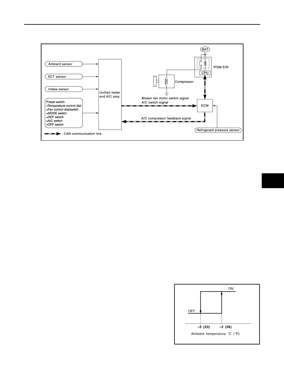
Unified meter and A/C amp. controls compressor operation by ambient temperature, intake air temperature
and signal from ECM.
SYSTEM OPERATION
When A/C switch, AUTO switch, DEF switch is pressed or when shifting mode position D/F, unified meter and
A/C amp. transmits A/C switch signal and blower fan motor switch signal to ECM, via CAN communication.
ECM judges whether compressor can be turned ON, based on each sensor status (refrigerant-pressure sen-
sor signal, throttle angle, etc.). If it judges compressor can be turned ON, it sends A/C compressor request sig-
nal to IPDM E/R, via CAN communication.
Upon receipt of A/C compressor request signal from ECM, IPDM E/R turns A/C relay ON to operate compres-
sor.
When sending A/C compressor request signal to IPDM E/R via CAN communication line, ECM simultaneously
sends A/C compressor feedback signal to ECM via CAN communication line.
ECM sends A/C compressor feedback signal to unified meter and A/C amp., then, uses input A/C compressor
feedback signal to control air inlet.
Compressor Protection Control
ECM makes the A/C relay go OFF and stops the compressor when pressure on the high-pressure side
detected by refrigerant pressure sensor is over approximately 3,119 kPa (31.8 kg/cm
2
, 452 psi), or below
approximately 118 kPa (1.2 kg/cm
2
, 17 psi).
Low Temperature Protection Control
Unified meter and A/C amp. turns compressor ON or OFF as judged by a signal detected by ambient sensor
and intake sensor.
When ambient temperature is higher than
−
2
°
C (28
°
F), the compres-
sor turns ON. The compressor turns OFF when ambient temperature
is lower than
−
5
°
C (23
°
F).
JSIIA1052GB
RHA094GB
Нет комментариевНе стесняйтесь поделиться с нами вашим ценным мнением.
Текст