Infiniti EX35. Manual — part 1473
VTL-10
< PRECAUTION >
PRECAUTIONS
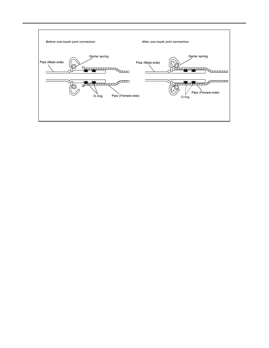
INSTALLATION
1.
Clean piping connection points, and insert male-side piping into female-side piping.
2.
Push inserted male-side piping harder so that female-side piping flare stretches garter spring.
3.
Garter spring seats on flare if inside diameter of garter spring becomes larger than outside diameter of
female-side piping flare. Then, it fits in between male-side piping cage and female-side piping flare to
anchor piping connection point.
NOTE:
When garter spring seats on flare, and fits in between male-side piping cage and female-side piping flare,
it clicks.
CAUTION:
• Female-side piping connection point is thin and easy to deform. Slowly insert the male-side pip-
ing straight in axial direction.
• Insert piping securely until a click is heard.
• After piping connection is completed, pull male-side piping by hand to make sure that connec-
tion does not come loose.
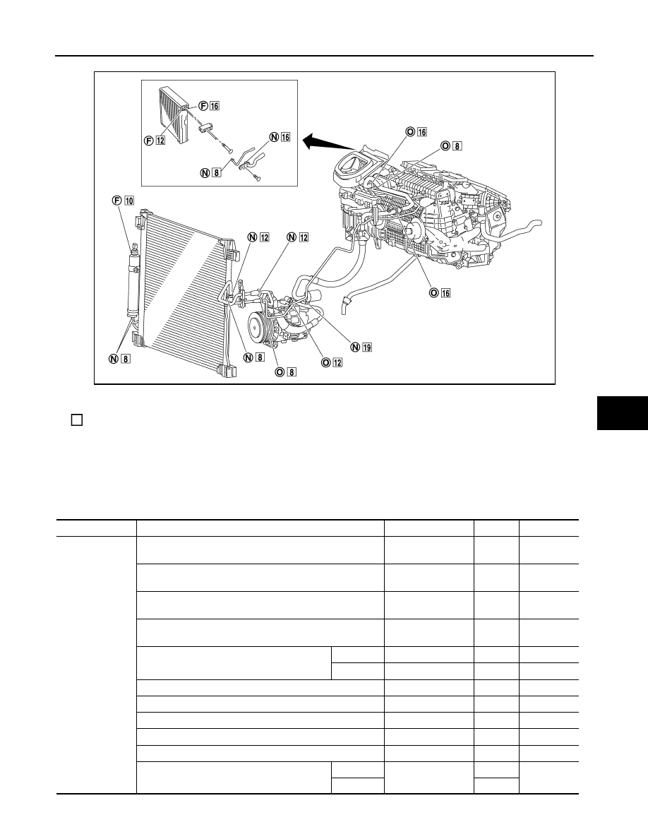
NOTE:
One-touch joint connection is used in points below.
• Low-pressure flexible hose to low-pressure pipe 2 (O-ring size: 16)
• Low-pressure pipe 1 to low-pressure pipe 2 (O-ring size: 16)
• High-pressure flexible hose to condenser pipe assembly (O-ring size: 12)
• High-pressure pipe 1 to high-pressure pipe 2 (O-ring size: 8)
• High-pressure pipe 1 to condenser pipe assembly (O-ring size: 8)
O-RING AND REFRIGERANT CONNECTION
SJIA0107E
PRECAUTIONS
VTL-11
< PRECAUTION >
C
D
E
F
G
H
J
K
L
M
A
B
VTL
N
O
P
CAUTION:
The new and former refrigerant connections use different O-ring configurations. Never confuse O-
rings since they are not interchangeable. Refrigerant may leak at the connection if a wrong O-ring is
installed.
O-Ring Part Numbers and Specifications
F.
Former type refrigerant connection
N.
New type refrigerant connection
O.
One-touch joint
:
O-ring size
JPIIA0711ZZ
Connection type
Piping connection point
Part number
QTY
O-ring size
New
Low-pressure flexible hose to low-pressure pipe 2 (One-
touch joint)
92473 N8221
2
16
High-pressure pipe 1 to high-pressure pipe 2 (One-touch
joint)
92471 N8221
2
8
Condenser pipe assembly to high-pressure flexible hose
(One-touch joint)
92472 N8221
2
12
Condenser pipe assembly to high-pressure pipe 1 (One-
touch joint)
92471 N8221
2
8
Condenser to condenser pipe assembly
Inlet
92472 N8210
1
12
Outlet
92471 N8210
1
8
Low-pressure pipe 1 to low-pressure pipe 2
92473 N8210
1
16
Low-pressure pipe 1 to expansion valve
92473 N8210
1
16
High-pressure pipe 2 to expansion valve
92471 N8210
1
8
Compressor to low-pressure flexible hose
92474 N8210
1
19
Compressor to high-pressure flexible hose
92472 N8210
1
12
Liquid tank to Condenser
Inlet
92471 N8210
1
8
Outlet
1
VTL-12
< PRECAUTION >
PRECAUTIONS
WARNING:
Check that all refrigerant is discharged into the recycling equipment and the pressure in the system is
less than atmospheric pressure. Then gradually loosen the discharge side hose fitting and remove it.
CAUTION:
Observe the following when replacing or cleaning refrigerant cycle components.
• Store it in the same way at it is when mounted on the car when the compressor is removed. Failure
to do so will cause lubricant to enter the low-pressure chamber.
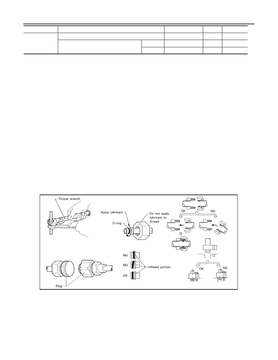
• Use always a torque wrench and a back-up wrench when connecting tubes.
• Plug immediately all openings to prevent entry of dust and moisture after disconnecting tubes.
• Connect the pipes at the final stage of the operation when installing an air conditioner in the vehicle.
Never remove the seal caps of pipes and other components until just before required for connection.
• Allow components stored in cool areas to warm to working area temperature before removing seal
caps. This prevents condensation from forming inside A/C components.
• Remove thoroughly moisture from the refrigeration system before charging the refrigerant.
• Replace always used O-rings.
• Apply lubricant to circle of the O-rings shown in illustration when connecting tube. Be careful not to
apply lubricant to threaded portion.
• O-ring must be closely attached to the groove portion of tube.
• Be careful not to damage O-ring and tube when replacing the O-ring.
• Connect tube until a click can be heard. Then tighten the nut or bolt by hand. Check that the O-ring is
installed to tube correctly.
• Perform leakage test and make sure that there is no leakage from connections after connecting line.
Disconnect that line and replace the O-ring when the refrigerant leaking point is found. Then tighten
connections of seal seat to the specified torque.
Service Equipment
INFOID:0000000003569892
RECOVERY/RECYCLING RECHARGING EQUIPMENT
Be certain to follow the manufacturer’s instructions for machine operation and machine maintenance. Never
introduce any refrigerant other than that specified into the machine.
ELECTRICAL LEAK DETECTOR
Be certain to follow the manufacturer’s instructions for tester operation and tester maintenance.
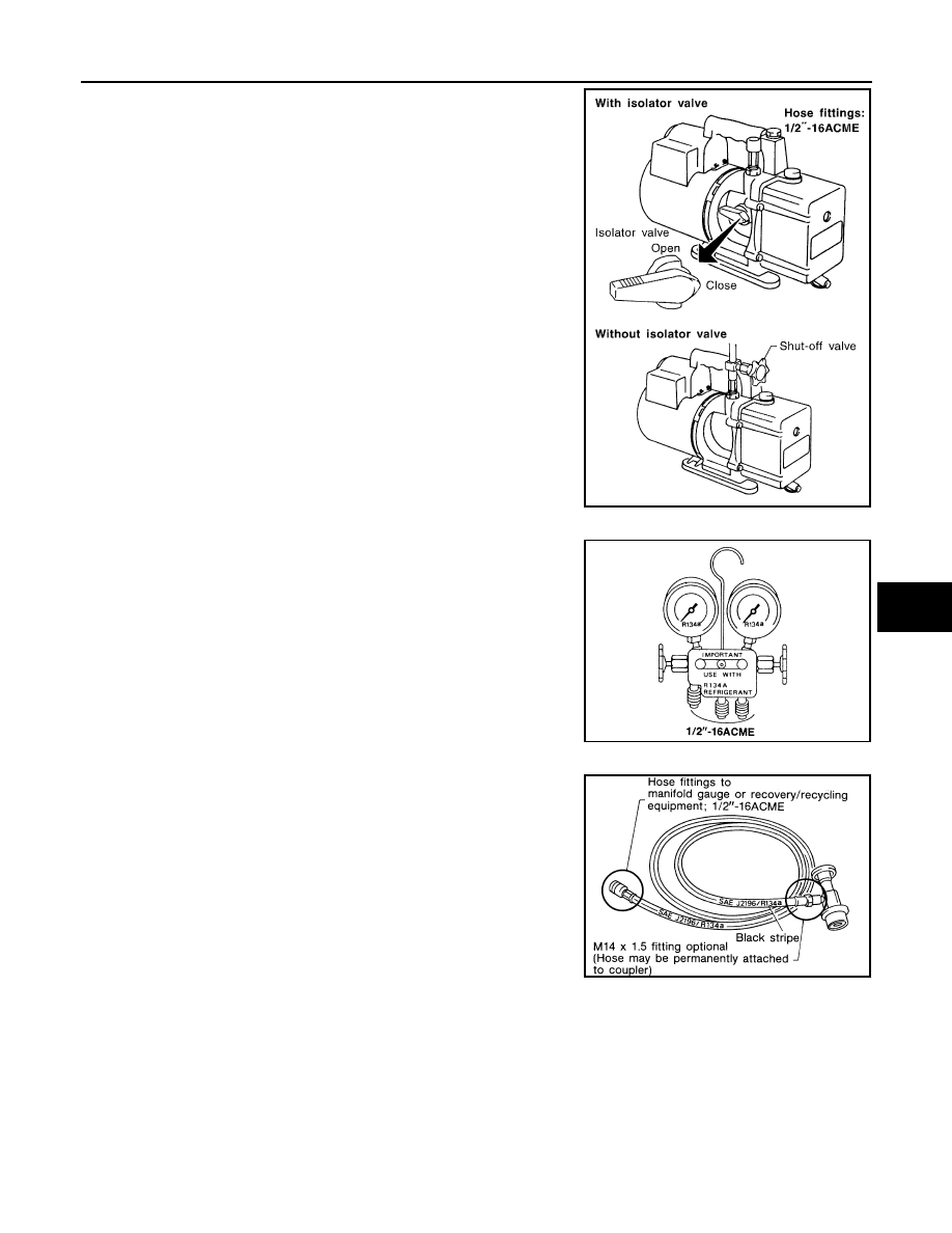
VACUUM PUMP
Former
Refrigerant pressure sensor to liquid tank
J2476 89956
1
10
Expansion valve to evaporator
Inlet
92475 71L00
1
12
Outlet
92475 72L00
1
16
Name
: NISSAN A/C System Oil Type S
Connection type
Piping connection point
Part number
QTY
O-ring size
RHA861F
PRECAUTIONS
VTL-13
< PRECAUTION >
C
D
E
F
G
H
J
K
L
M
A
B
VTL
N
O
P
The lubricant contained inside the vacuum pump is not compatible
with the specified lubricant for HFC-134a (R-134a) A/C systems.
The vent side of the vacuum pump is exposed to atmospheric pres-
sure. So the vacuum pump lubricant may migrate out of the pump
into the service hose. This is possible when the pump is switched
OFF after evacuation (vacuuming) and hose is connected to it.
To prevent this migration, use a manual valve placed near the hose-
to-pump connection, as per the following.
• Vacuum pumps usually have a manual isolator valve as part of the
pump. Close this valve to isolate the service hose from the pump.
• Use a hose equipped with a manual shut-off valve near the pump
end for pumps without an isolator. Close the valve to isolate the
hose from the pump.
• Disconnect the hose from the pump if the hose has an automatic
shut-off valve. As long as the hose is connected, the valve is open
and lubricating oil may migrate.
Some one-way valves open when vacuum is applied and close
under no vacuum condition. Such valves may restrict the pump’s
ability to pull a deep vacuum and are not recommended.
MANIFOLD GAUGE SET
Be certain that the gauge face indicates HFC-134a or R-134a. Be
sure the gauge set has 1/2
″
-16 ACME threaded connections for ser-
vice hoses. Confirm the set has been used only with refrigerant
HFC-134a (R-134a) and specified lubricants.
SERVICE HOSES
Be certain that the service hoses display the markings described
(colored hose with black stripe). All hoses must equip positive shut-
off devices (either manual or automatic) near the end of the hoses
opposite to the manifold gauge.
SERVICE COUPLERS
RHA270DA
SHA533D
RHA272D
Нет комментариевНе стесняйтесь поделиться с нами вашим ценным мнением.
Текст